基于网络编码的多信源组播通信系统,包括源代码,原理图等

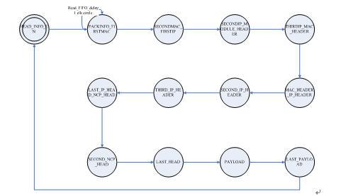
图3 .2-10coded_process状态机
uncoded_process 
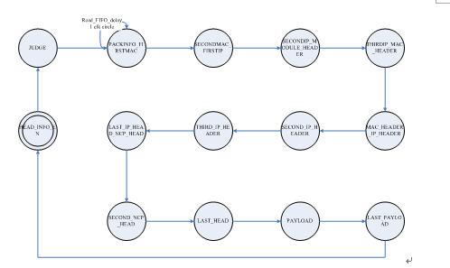
图3.2-11 uncoded_process 状态机
5、Output arbiter
① 本模块输入输出信号列表及说明
| Signal name | Bit width | Input or output | Description |
| Out_data_out_0 | 64 | input | input data bus from "packing center" |
| Out_ctrl_out_0 | 8 | Input | input ctrl bus from "packing center" |
| Data_val_out_0 | 1 | Input | 1=data from packing center to output arbiter is valid, 0=otherwise |
| Rdy_out_0 | 1 | output | 1=output arbiter is ready to receive from packing center, 0=otherwise |
| Out_data_out_1 | 64 | input | input data bus from "input arbiter 1" |
| Out_ctrl_out_1 | 8 | Input | input ctrl bus from "input arbiter 1" |
| Data_val_out_1 | 1 | Input | 1=data from input arbiter 1 to output arbiter is valid, 0=otherwise |
| Rdy_out_1 | 1 | output | 1=output arbiter is ready to receive from input arbiter 1, 0=otherwise |
| Out_data_out_2 | 64 | input | input data bus from "input arbiter 2" |
| Out_ctrl_out_2 | 8 | Input | input ctrl bus from "input arbiter 2" |
| Data_val_out_2 | 1 | Input | 1=data from input arbiter 2 to output arbiter is valid, 0=otherwise |
| Rdy_out_2 | 1 | output | 1=output arbiter is ready to receive from input arbiter 2, 0=otherwise |
| Out_data_mac | 64 | output | output data bus to "MAC Layer" |
| Out_ctrl_mac | 8 | Output | output ctrl bus to "MAC Layer" |
| Data_val_mac | 1 | Output | 1=data from output arbiter to MAC layer is valid, 0=otherwise |
| Rdy_mac | 1 | Input | 1=MAC layer is ready to receive from output arbiter, 0=otherwise |
| clk | 1 | Input | System clock running at 125MHz |
| Rst_n | 1 | input | System asynchronous reset signal |
② 功能描述及数据流
本模块为输出仲裁模块。为协调多路输出通道,避免冲突而设计。入端构建与input arbiter通信的两路端口和与packing通信的一路端口,出端构建与MAC层通信的输出端口。将选通并维护唯一一条输入通道直至该数据包全部发送完毕。采用轮询方式检查三路输入通道以避免冲突。
③ 关键时序及状态机

图3.2-12 Output arbiter状态机
3.3 转发路由器详细设计方案
3.3.1转发路由器系统整体模块图

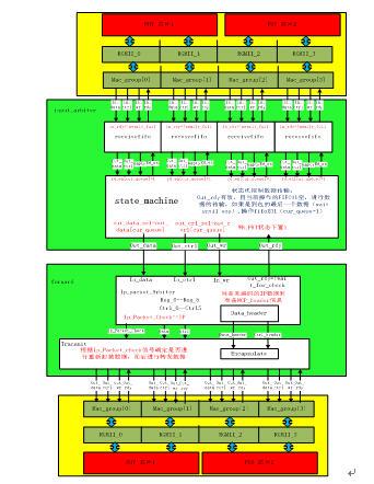
图3.3-1总体模块图
系统模块功能说明:该模块有两个子模块input_arbiter模块和forward模块构成,其中前者为标准模块;后者为自定义模块,接受来自MAC层的数据包,经过相关处理输出数据包,实现将未编码的IP数据包封装成NCP数据包并进行转发以及将其它非IP数据包或NCP数据包进行直接转发的功能。
3.3.2系统中各单元模块的功能与时序
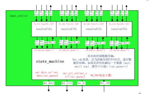
Input_arbiter模块① Input_arbiter模块的内部结构图如图3.3-2

图3.3-2 input_arbiter模块
② 本模块的输入输出信号列表及说明(如下例)
| 信号名称 | 位宽 bits | I/O | 描述 |
| in_data_n(n:0、1、2、3) | 64 | input |
- 一种基于电力线的家庭以太网络实现方法(10-10)
- 基于DSP和FPGA的机器人声控系统设计与实现 (04-16)
- 面向大众市场的千兆位级收发器(05-04)
- 利用以太网硬件在环路实现高带宽DSP仿真(05-04)
- 采用软处理器IP规避器件过时的挑战(05-04)
- WCDMA系统基带处理的DSP FPGA实现方案(01-02)
