一步一步学ZedBoard Zynq(四):基于AXI Lite 总线的从设备IP设计
本小节通过使用XPS中的定制IP向导(ipwiz),为已经存在的ARM PS 系统添加用户自定IP(Custom IP ),了解AXI Lite IP基本结构,并掌握AXI Lite IP的定制方法,为后续编写复杂AXI IP打下基础。同时本小节IP定制方法同样适用于MicroBlaze处理系统。
本小节定制的是简单LED的IP,只有一个数据寄存器,向其写值就可以控制8个LED相应亮灭。
硬件平台:Digilent ZedBoard
开发环境:Windows XP 32 bit
软件: XPS 14.2 +SDK 14.2
一、创建ARM PS系统
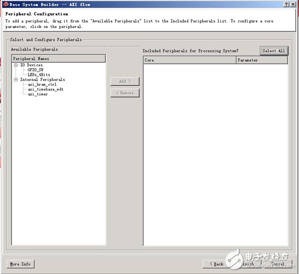
同前面几节一样,首先使用XPS创建ARM PS系统。需要注意的是,在选择外设时,同样不要添加任何外设
二、定制AXI IP
ARM PS系统创建结束后,就可以开始定制用户自定义IP。XPS提供了Create or Import Peripheral Wizward 向导,使得用户自定义IP的创建变得非常简单。当然在熟悉了AXI IP核结构和代码编写规则后,可以直接编写自己的IP核而不使用向导。这里采用向导方式。
1、产生AXI IP外设模版
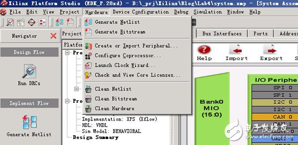
Hardware->Create or Import Peripheral Wizward ,启动向导
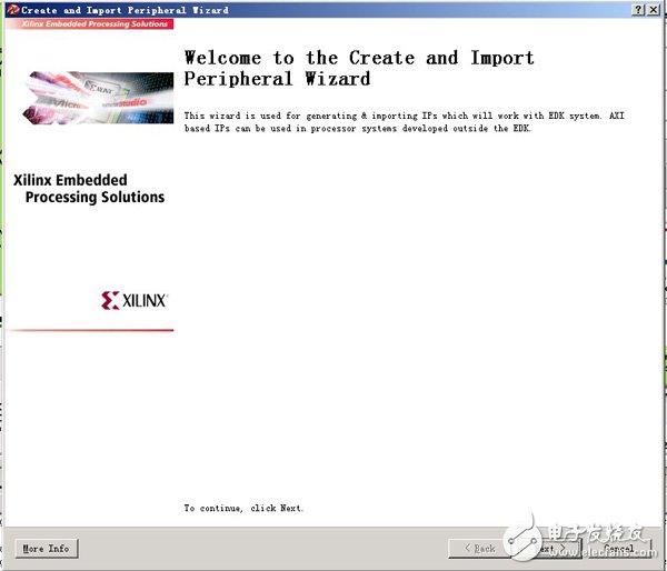
欢迎界面
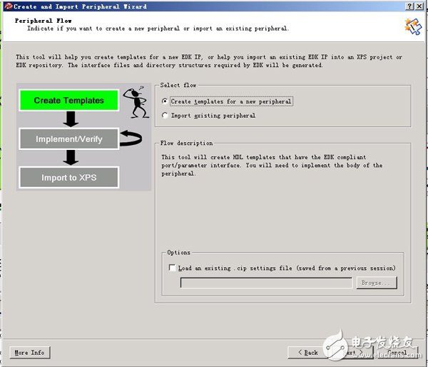
选择从模板创建新外设
默认是将外设直接包含到当前XPS工程中
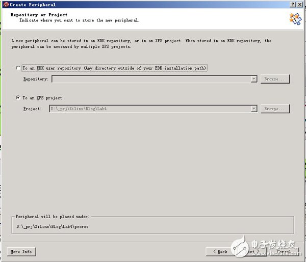
填入外设名。注意必须都是小写。这里我们建立的是my_axi_ip。下面是版本控制,可以根据需要修改。同时面板的最下方还提示了将创建名为my_axi_ip_v1_00_a的库(其实就是一个目录),所有实现这个IP的HDL文件都在这个库中。
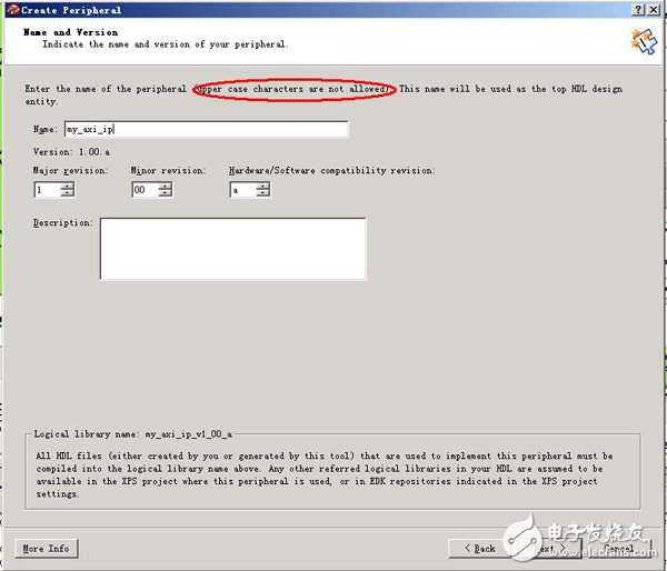
接下来要选择外设总线的类型。AXI4_Lite为最基本的AXI 总线,用于简单处理,所有空间访问都是通过地址/寄存器方式访问,不支持突发;AXI4是标准AXI4总线标准,支持突然,支持高速;AXI4_Stream专门为数据流而设计。
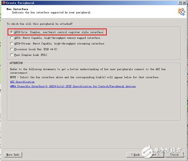
在IPIF (IP 接口) 配置,这里配置接口的一些属性,如是否是AXI 主/从设备等。我们所定制的IP是一个从设备,因而不需要使用主设备接口。
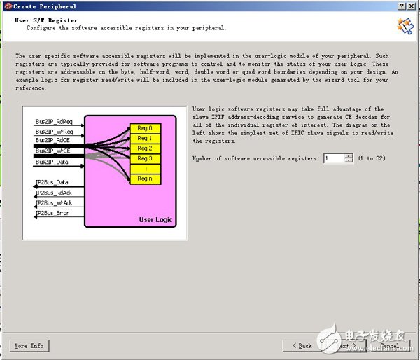
选择需啊哟的寄存器数量。因为我们只需要一个数据寄存器,这里选1。
接下来就是IPIC(IP 互联),也就是IP的接口信号。以BUS2开头的信号,意味对IP来说,这些信号是输入信号;同样IP2BUS意味着输出信号。
这里一些信号做一些说明。
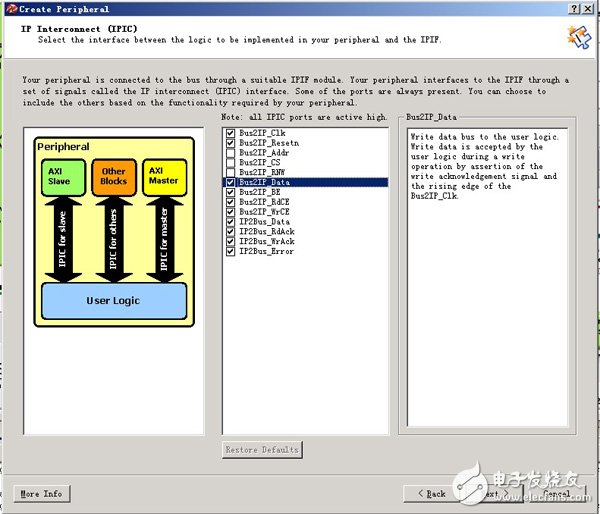
BUS2IP_WrCE(Write Chip Enable,写使能)
AcTIve high chip enable bus to the user logic. These chip enables are asserted only during acTIve write transacTIon requests with the target address space and in conjuncTIon with the corresponding sub-address within the space. Typically used for user logic writable registers selection.
BUS2IP_Data(Write Data,写数据)
Write data bus to the user logic. Write data is accepted by the user logic during a write operation by assertion of the write acknowledgement signal and the rising edge of the Bus2IP_Clk.
BUS2IP_BE(Byte Enable,字节使能)
Byte Enable qualifiers for the requested read or write operation to the user logic. A bit in the Bus2IP_BE set to '1' indicates that the associated byte lane contains valid data. For example, if Bus2IP_BE = 0011, this indicates that byte lanes 2 and 3 contain valid data.
IPBUS2_RdAck(Read Acknowledgement,读反馈)
Active high read data qualifier providing the read acknowledgement from the user logic. Read data on the IP2Bus_Data bus is deemed valid at the rising edge of the Bus2IP_Clk and IP2Bus_RdAck asserted high by the user logic.
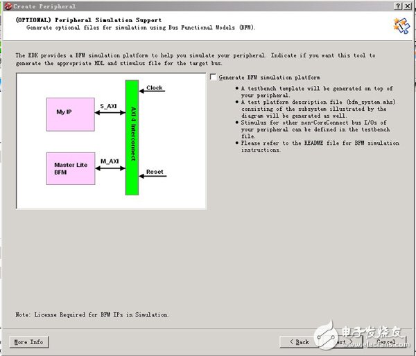
接下来需要使用需要使用BFM (Bus Functional Models, 总线功能模型)对外设进行仿真。本例IP很简单,不要使用。
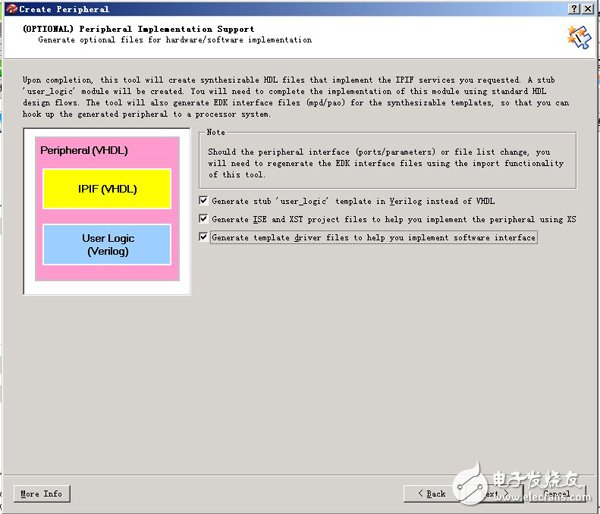
最后,需要选择HDL类型、ISE工程支持和软件驱动模板。因为我比较习惯使用verilog,因而使用verilog模板。需要说明的是,IP接口仍然是VHDL编写,只是用户逻辑改用verilog。如果不需要使用软件驱动模板的话,可以不选上。这里选上了,但是后续编程的时候我并没有用。
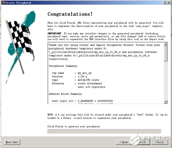
最后给出了外设的信息summary。支持,my_axi_ip"外壳"基本完成。后续我们只需要对user_logic进行编写,并修改元件引脚即可。
2、编写IP
修改.mpd文件,在目录
Lab4\pcores\my_axi_ip_v1_00_a\data\
###################################################################
##
## Name : my_axi_ip
## Desc : Microprocessor Peripheral Description
## : Automatically generated by PsfUtility
##
###################################################################
