静态时序分析(STA)
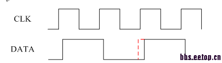
在后仿时,因为DATA经过延时单元(buf),高电平脉宽从黑色的部分增加到红色的部分,会引起时序(setup)违例或者采错信号(本来为低电平,采到高电平)。
这种情况静态时序分析时,会检查吗?PS:我做静态时序分析时没有问题,在带时序的后仿才检查出这种错误。
会,如果没有查到,要么是sdc的问题,要么是你的仿真于sdc不符
Clock synchronization logic : STA cannot detect the problem of clock generation logic not matching the clock definition. STA assumes that the clock generator will provide the waveform as specified in the clock definition. There could be a bad optimization performed on the clock generator logic that causes, for example, a large delay to be inserted on one of the paths that may not have been constrained properly. Alternately, the added logic may change the duty cycle of the clock. The STA cannot detect either of these potential conditions.《Static Timing Analysis for Nanometer Designs A Practical Approach 》
这段话可以解释STA不检查上述问题吗?
8k的时钟作为CLK,而DATA是8K的二分频信号与其他信号组合产生的。
DATA信号的占空比发上变化
你是不是set_false_path了啊?那样当然有路径会出错,STA却不报...
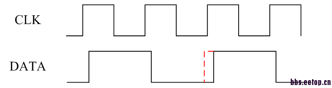
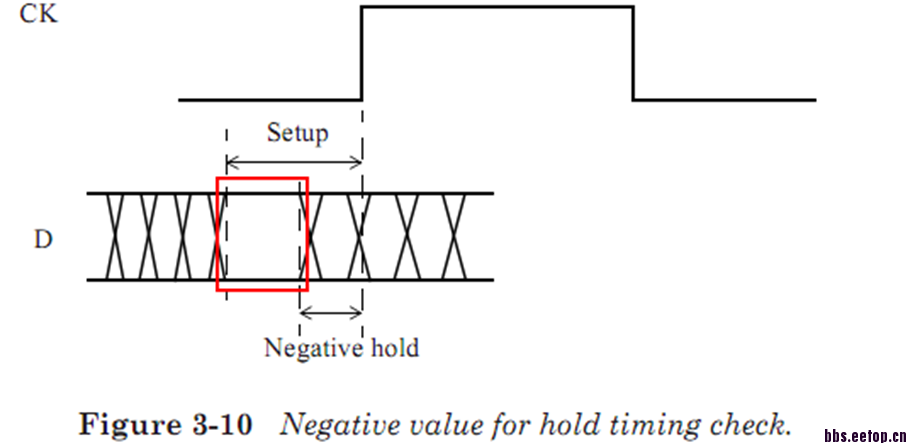
这个问题涉及到负延迟,如图二,只要数据在红色框内不变化,数据都能正确的采到。在STA中是可以识别负延迟的,认为采集到的数据是低电平(实际也是采到低电平)(图一)。但是在modelsim中,不识别负延迟,而是把负延迟标记0.所以在modelsim中认为应该采集高电平但是高电平又不满足建立时间,所以报错。
是不是这样?求正解
markyixia