impdance matching on pa
There must be something wrong with my understanding of impedance transformation.
Anybody can explain why this happens and how to design the impedance transformation network?
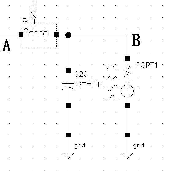
is the load impedance is 50ohm or 250 ohm
khouly
250ohm
did u make the impedance of the port to be 250 ohm , or it is 50 ohm
khouly
Yes, I made it 250ohm.
what is the frequency of operation
khouly
fo=433MHz
make the inductor 164 nH and the capacitor 1.9 pF
khouly
Thank u very much. I am so careless.
I calculated it directly on calculator without writing down the process,which lead to a falsed value.
RF really needs careful step-by-step analysis and deduction.
The exact value should be 1.73pF 168.7nH.
Thanks again.
u welcome , but u need to read any article about impedance matching using smith chart , it will help u alot in designing these networks
khouly
I have read some, but I don't know whether it is suitable for my application.
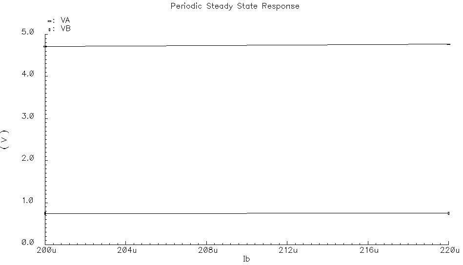
I simulated my PA with the Chokes and Inductors replaced with murata models and the output power decreased about 1dB. Do u have any suggestions in practical design?
For example, PCB, practical loadpull and other.
Added after 7 minutes:
khouly,
Another question:
Do u know the harmonic requirements in constant wave modulation method(mine is FSK) or have any articles about that?
How much lower the second and third harmonic should be than the 1st?
yeah , when u use the models sure the power will degrade coz the loss of the inductors and the parasitic capacitances , u need to get high quality factor inductors.
about the PCB check this link
http://pesona.mmu.edu.my/~wlkung/ADS/ads.htm
about the harmonic requirements u should know that from the receiver performance
khouly