Antenna pcb in commercial key fob
Can anyone tell me what kind of antenna in some key fob.
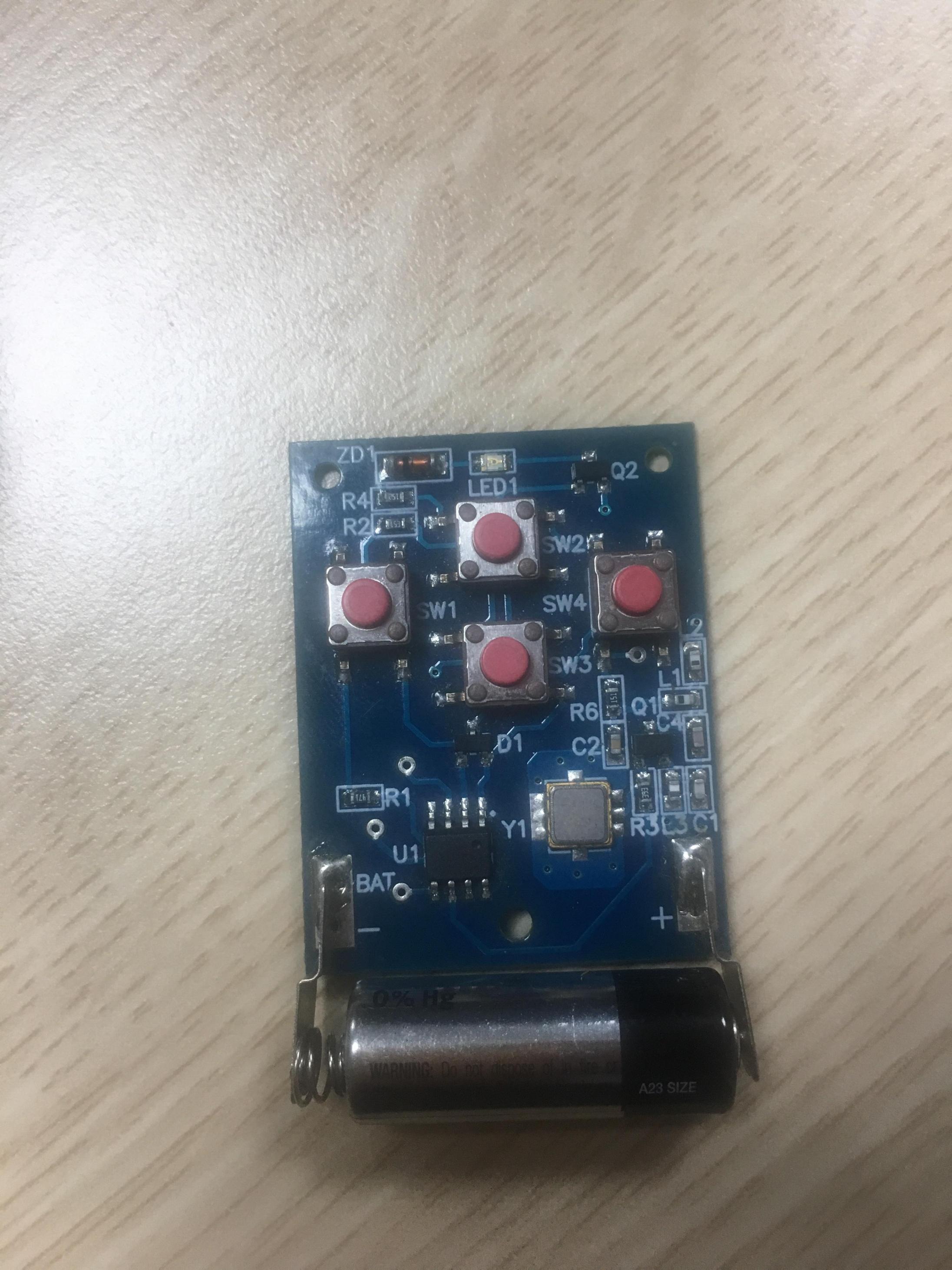
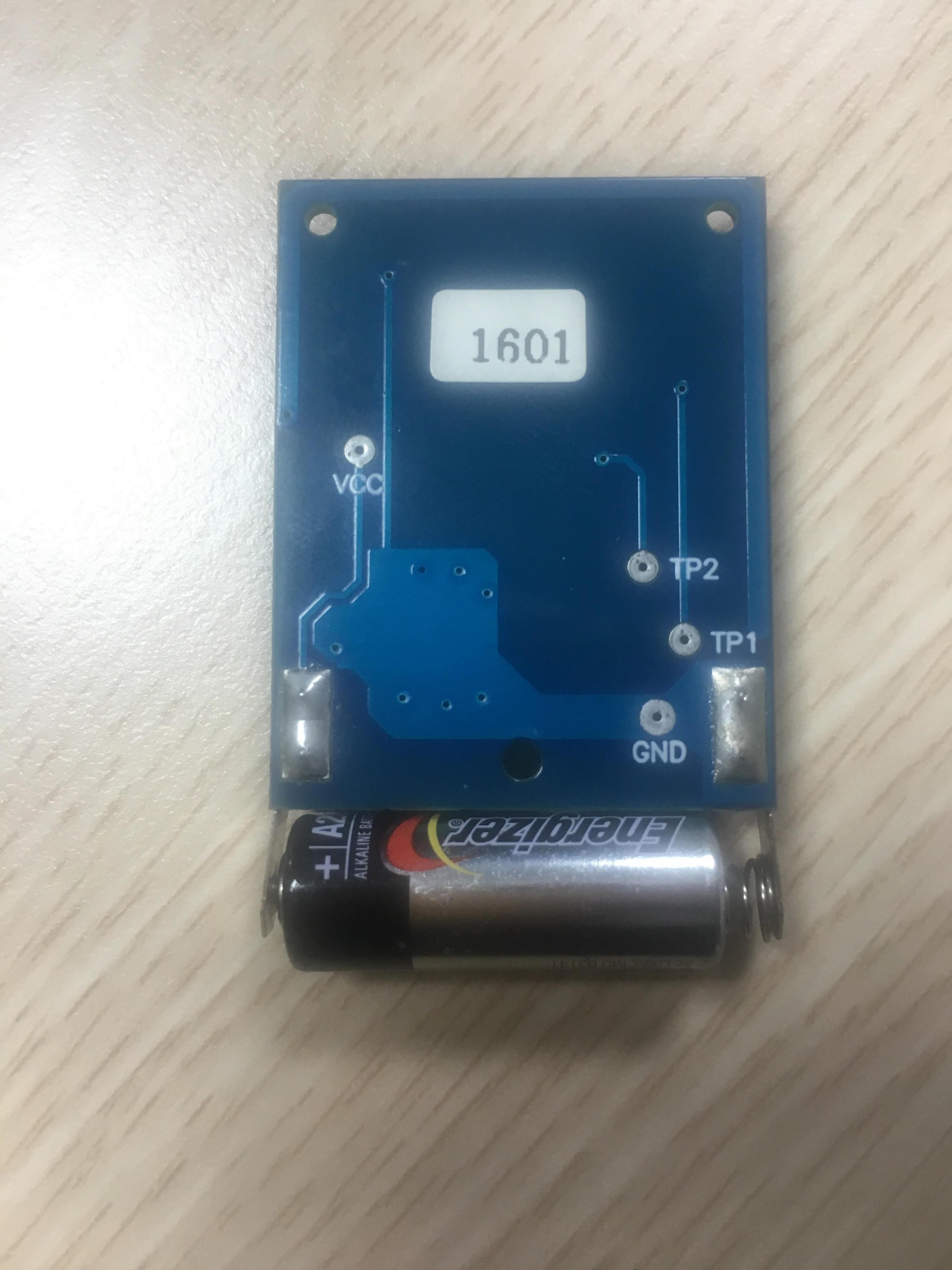
As i can see, it is just a trace which is 7.5 cm length (the frequency 315 MHz)
I attach the image of keyfob below, can anyone explain to me how it work and some related formula to design with another frequency.
Thanks.
Nothing special, a short (< λ/4) folded monopole, tuned with series inductor L2. Small bandwidth, high Q, not very efficient.
Can be used at different frequencies (434 or 915 MHz) bei changing the matching network.
Can you tell me some documents and formulas to calculate the value of series inductor and matching network.
I am overwhelmed by documents that I search in the internet and I dont know what is exactly
Thanks
https://infocenter.nordicsemi.com/pdf/nwp_008.pdf
http://www.ofdma-manfred.com/wp-cont...2/09/23-MB.pdf
Can you explain more insight in the antenna in the picture. Example, if I want to switch to 433Mhz in this circuit while remain the length of trace antenna. How I tuning the L2 value
You'll determine the antenna impedance by measurement or simulation, then design the matching circuit.
does matching circuit have huge impact on resonant frequency
I simulated the short antenna (length = lambda / 10) with L component right after the feed point. However, i felt it was too hard to resonate at 433 MHz (I used HFSS to simulate)
Hi guys,
I found this document. In the "Short PCB Stub", they said that "If the trace runs parallel
to ground, the real part of the antenna impedance will be
approximately 10 ohms. In a hand-held unit, the impedance
will be raised substantially through hand effects. For a tenth
wavelength strip on a board with hand effects included, the
antenna has a capacitive reactance of about 150 ohms"
Is that correct, I can not simulate to calculate the impedance of this antenna.
The document I attached below
RFM_antenna.pdf
The order of magnitude sounds reasonable. Obviously the numbers have been empirically validated, but your antenna geometry may be different.
You can try different inductance values and measure the received field strength.