difficulty in matching off the shelf GPS antenna
I encounter this difficulty when matching my off the shelf GPS antenna to 50 ohm.
hope someone could tell me whats when wrong and how to debug.
so the original load impedance was shown in the pic below.
i have a "series-shunt-series-shunt" matching circuit before my GPS antenna. series component was replaced with 0 ohm and below are the measured impedance(highlight in yellow).

then i tried to matching the antenna by using series/shunt inductor for my first component. i tried a few value so below are the measured impedance.
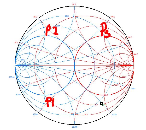
then i try to used 2nd component (series/shunt) to try matched it to 50 ohm. but when i place the second component, the impedance just wouldn't move, it just sit at the points almost the same as the first components, i have used the value based on the simulation tools and try a few other value too. i tried 3 set of matching circuit based on the pic i sent above, but all same, it just couldn't matched to 50 ohm when i place the 2nd matching component.
can someone enlighten me what happened in this case. is it some parasitic that causing it not able to match to 50 or close to 50 ohm?
i have follow all the recommend design from the off the shelf GPS, antenna placement, board size, matching circuit layout bla bla bla..
hope someone here can point out the issue or tell me how to debug it.
thanks.
Antenna impedance or suggested load impedance? Measured value or datasheet specification? Is it a passive antenna that allows impedance measurements without special provisions?
Please show the implemented circuit. How did you measure impedance?
Im unable to relate the shown Smith charts to usual matching methods.
To match the GPS antenna follow the next steps:
1. Using a VNA, measure the impedance of the antenna at GPS frequency.
2. Using the RF impedance matching software (or an online impedance calculator), find the the LC impedance network and its values.
Ideally would be that in your RF circuit simulator to use the S-parameters of the LC components provided by the manufacturer, which includes the components parasitics.
https://ds.murata.co.jp/simsurfing/i...tml?lcid=en-us
For GPS (which is a narrow band system) usually should be enough to use a series L, shunt C, impedance matching network.
https://www.analog.com/en/design-cen...lculator.html#
3. At the end, implement the matching network circuit, and measure the return loss (or VSWR) of the antenna including the matching circuit.