Patch bowtie matching problem
Could you post an image? There are many possible configurations. Possible reasons: wrong feeding, wrong ground plane, but need more information on your design.
p.s. I think coplanar feeding bowtie slots are simple to optimize.
It is not slot antenna. By the way I didnt use ground plane at the back.
I ve used now after your post but there is no significant change in s-parameter.
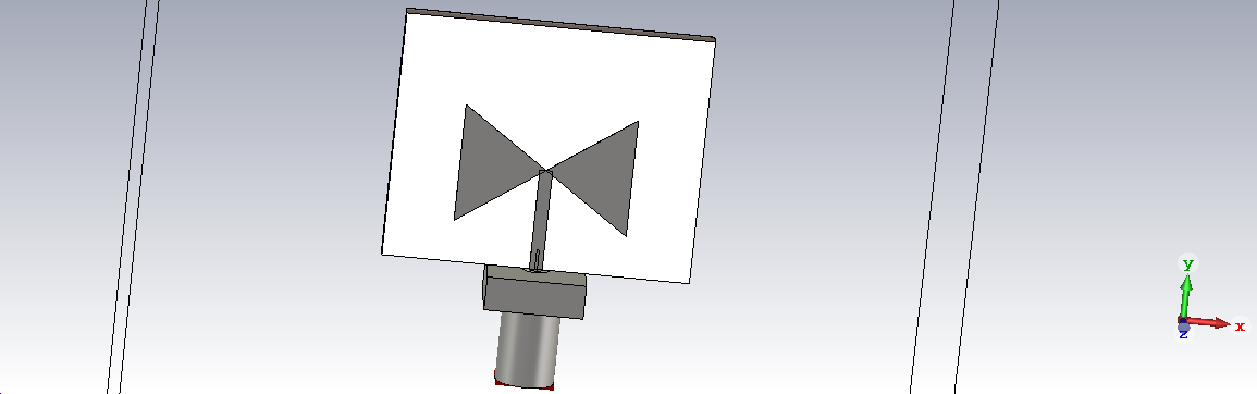
A bow-tie antenna is a dipole antenna, but the picture seems to show a monopole antenna. It may work somehow as an antenna, but surely not with the useful wide band characteristic expected from a bow-tie.
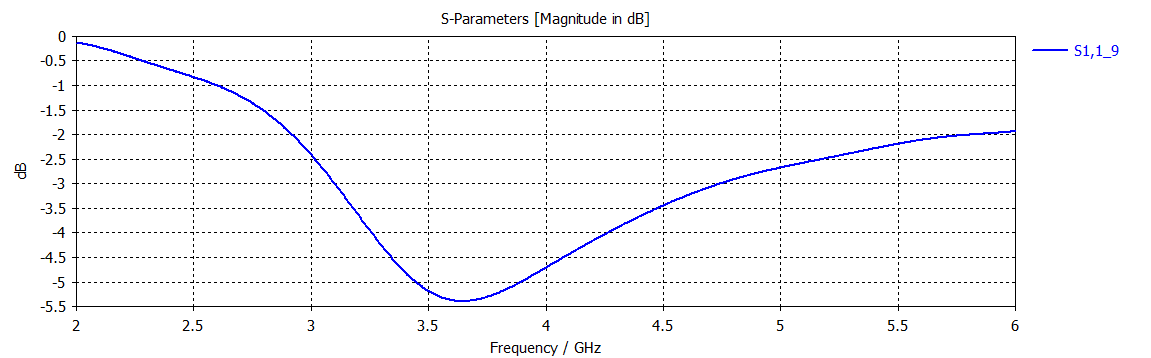
Anyway, before designing a matching circuit, you should look at the input impedance curve.
it is acting like a monopole cuz the transmission line, right? but otherwise how can i feed the antenna? i dont want to use center-fed. there are some articles used transmission line in bowtie. My design procedure is like that, first design a bowtie antenna by using discrete port in the center (so there is no transmission line at this point) and then by considering input impedance, i design a transmission line.
By the way the wideband characteristic could be because of not using ground plane? cuz when i simulate the same antenna with ground plane still get s-parameter like -4 or -5dB but the curve shape is more sharp at the end and has kinda narrowband characteristic.
So what can i do to fix that? 😕 i will use ground plane 🖒 if you give any other tips that would be great. Also i didnt get the problem of the transmission line being connected to bowtie? Isn't it how it suppose to be feed?
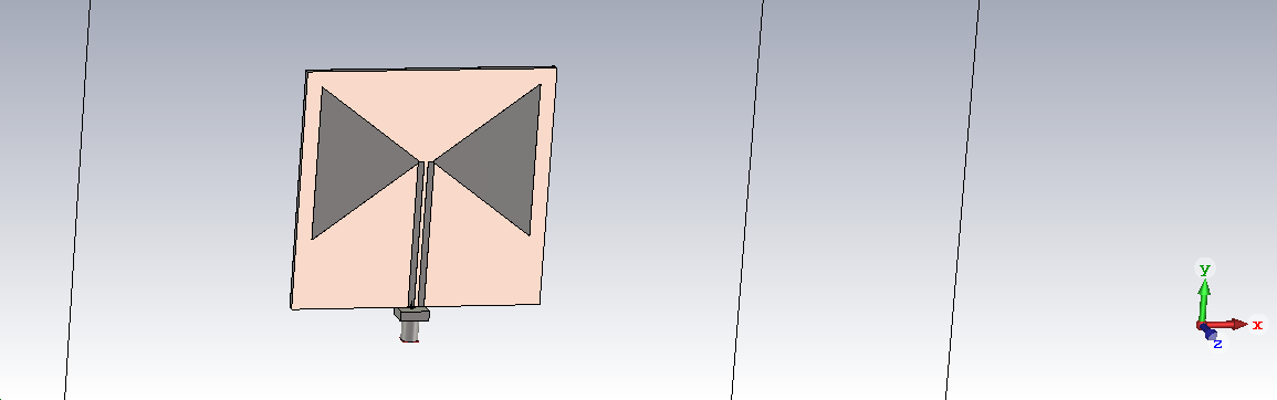
But your microstrip lines "signal" conductor is connected to BOTH legs of the bowtie. This does not create a differential signal between the two arms.
As FvM stated, you created a monopole antenna.
For Bowtie, you want to connecting signal conductor to one side, and ground conductor to the other side.
Here is an example including the microstrip balun:
i saw couple of designs like that but can i design it without balun structure? cuz probably it will be a bit challenging for me to design it.
you mean for each arm there should be 2 transmission line? but i saw a paper that used single feed :/ here is the picture

There are many papers out there that make no sense. If one line feeds both arms with the same phase, it is not a bowtie antenna.
i've tried 2 transmission line for both arm (remade from an article). Is it okay? i get better s-parameter result around -30dB and there is no ground plane cuz i dont know where to place the via like which arm or anywhere else... anyway this design works but dimensions are very big for my work
Add a 1:1 balun where you go from unbalanced coax to balanced symmetric line.
Also have a look at the alternative design in post #7
Presume you want the bow-tie as wide band (e.g. 1:2) antenna, you also need a wideband balun, e.g. a transformer. λ/2 transmission line (as in post #7) is only good for small band.
balun is necessary? cuz i never design a balun structure and kinda scares me Im getting good results by using 2 transmission line design, it has vertical polarization just like a bowtie and s-parameter is like -30dB. but gain is still not that good (around 2). If u have any suggestion to increase gain that would be really great..
In real world: yes. Otherwise your antenna will be sensitive to touching the coax feed.
thanks, i didnt know that. Is there any source you can suggest me to look at for balun design?
maybe this be useful: https://www.hindawi.com/journals/ijap/2013/651040/
I suggest to simulate separate blocks first. Feeding line with two ports, ensure S21 is good over required bandwidth, and no radiation losses. With some simple ports, then add two SMA ports. Finally use one SMA port and bowtie. Are you sure feeding line impedance is matched to SMA connector? Try to increase feeding line length by λ/4, if S11 become much worse, then something is not matched (bowtie to feeding line, feeding line to SMA connector).
i've tried to increase the length by λ/4 as u said, there were no significant change in s11. and im doing the simulations of the single transmission line rgt now. Thank u for the suggestions one problem is that antenna is fed through the left transmission line and the other transmission line + bowtie arm is fed by that line. this shifts the radiation pattern to the left which something i dont want to. Is it okay to feed the antenna like this? here is the image
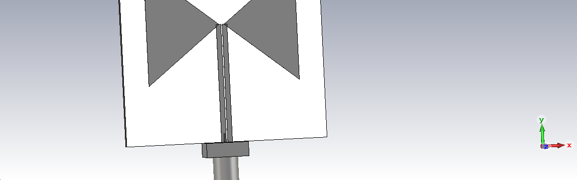
By adding the balun, you get a symmetric feed for symmetric radiation pattern.
You are talking about "λ/4" but show a 1:3 frequency range in post #3. What's the antenna specification you want to achieve? If it's wideband, λ/4 is meaningless.
Without balun, the feed line will act as part of the antenna and affect the radiation characteristic, as apparently observed in your latest design.