GPS matching network confusion
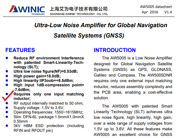
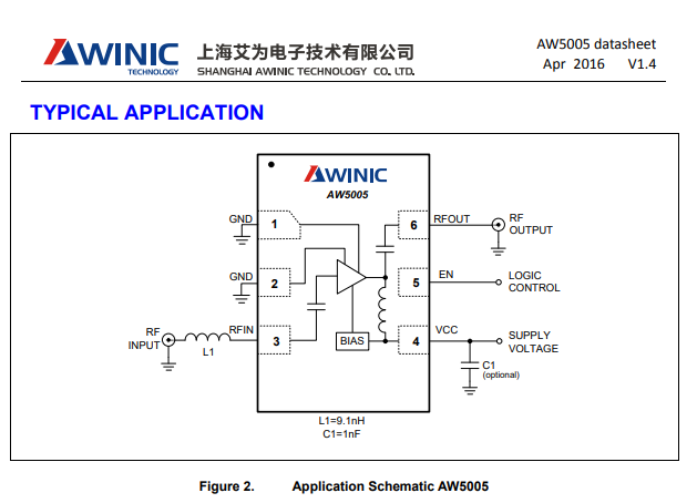
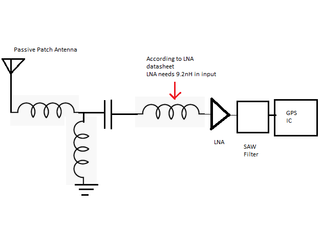
Patch antenna manufacturer has given me a T-matching type of circuit which i have to place just after patch. Where as LNA datasheet says that a 9.2nH inductor is needed at input. LNA manufacturer datasheet says that before 9.2nH it can be a 50ohm input line.
So my confusions are
1. Is my attached circuit diagram correct?
2. How is the matching process going to happen? Is it like designer's task is to match the impedance 50ohm upto after T network(before the 9.2nH) and expect that 50ohm input->9.2nH->LNA path is already optimum?


I believe that the manufacturer has assumed the IC will be used with 50 Ohm source impedance that's why a single inductor completes the matching for Lowest Noise.
The 9.2nH in series before LNA is to obtain less reflection (with respect to either 50 or 75 OHM, but 50 OHM is more common for LNA). Then it is easier for the user to design the transmission line to another place. The idea of the T-matching for the patch antenna is the same. The matching network given by the manufacturer is obtained on their evaluation board. The end users need to fine tune the values to get the optimal performance unless the same PCB stack-up and layout are used.
So I would like to comment:
1. Your design is sufficient, there are four components for tuning. In theory two components are enough for narrow band signal, while more components may give you wider matching bandwidth;
2. As a start point, put the values given by the manufacturers into the design. Take extreme care with the layout. When the prototype board is ready, replace the T-matching network with straight path (remove shunt inductor, replace series inductor/capacitor with 0R resistor or 100nF capacitor if AC-coupling is required for LNA). Then use VNA to measure the impedance at the antenna T-matching place. Measure the impedance both towards antenna and towards LNA. Then use the T-matching network to do conjugate impedance matching. This will always give you the BEST results.
