what's the rf cavity filter tuning principle
I can't search suitable information from internet,I want to know the tunning principle and tunning rules,
especially for extending or narrowing frequency,not shift frequency beacause I know f=1/2π√LC.
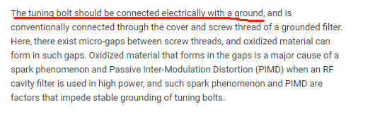
when I mount cover on the housing,is them shorted?I means the tunning bolt shorted with housing(ground)
because they are all metal.thank you!
The tuning method can be basically described as variable capacitance. To understand the whole filter design, including the tuning options, you should read more about cavity filters.
https://d1jiktx90t87hr.cloudfront.ne...-July_2017.pdf
http://www.av.it.pt/medidas/data/Man...ain_tuning.pdf
http://literature.cdn.keysight.com/l...980-2785EN.pdf
http://www.emrcorp.com/uploads/b70c8...ors(54-67).pdf
I know it will change the value of the capacitor when rotating the tunning bolt, and then the frequency will change.
I have two mainly question:
1.what's the principle of adjusting passband, I know it can be tuned by the rotating bolt which is not above the resonator,but I don't know
the principle.
2.the equivalent circuit of a filter is a group RLC circuit,why the cover is shorted with the housing?I think this means the two ends of the capacitor is shorted,
it confused me.
thank you, your links are useful. I need more time to understand them because English is not my mother language
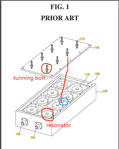
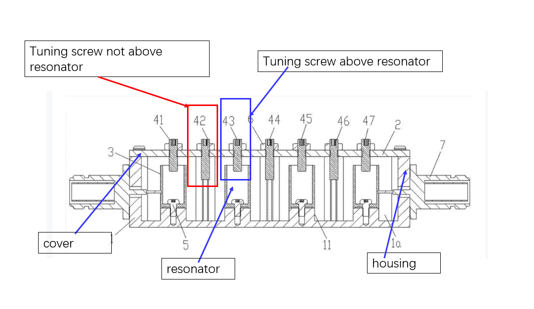
Your colored hand sketched annotation of the drawing makes no sense, particularly the blue circle around a coupling slit. There's no tuning bolt in this position.
Why don't you provide a readable cross section drawing of the resonator you are talking about?
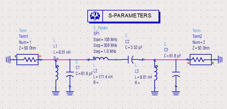
The LC circuit doesn't fit the cavity filter. Think about shunt LC resonators and series coupling capacitors, although a lumped equivalent circuit doesn't exactly fit.
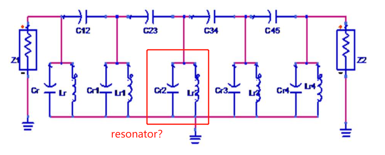
Thanks for your reply.I just get an example of cavity filter and circuit,that circuit is not the equivalent circuit of that filter.
I want to make my question more clearly,so I add that circuit.
I download a crossing draw of a filter and a circuit,they are not matched,just for a question reference.
The screws in the blue rectangle can be used to adjust passband,is this correct?If this is correct,what's the rules and principle?
In the circuit draw,is the part in the red rectangle a resonator circuit? Why the cover should be shorted with the housing,in my understanding,it's like
the two ends of one capacitor are shorted.I don't know if my understanding is correct.Maybe the circuit is not exactly same with the real filter.
Hi thank you for your links.
I know more about the tunning method.And I also know why the bandwidth will change when I tuning the coupling apertures.
Do you have some links about the basic structure of a cavity filter? I still can't match the circuit with the object.I don't know which part represents the positive end of the capacitor,
and what's the signal transmission sequence in a complicated filter housing,for example a DTMA.
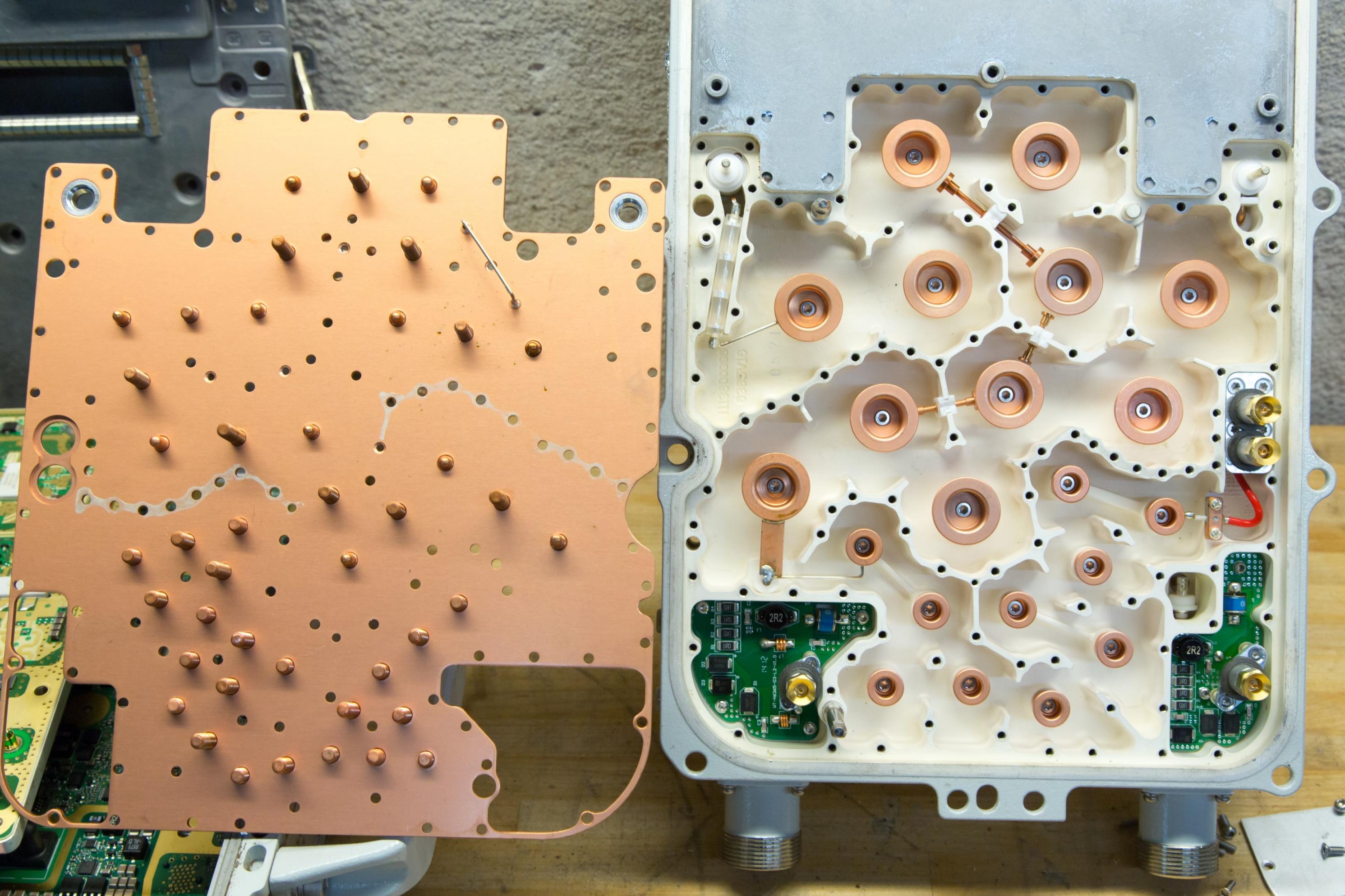
I was lately seeing post #7. I would prefer a 3D drawing to confirm that the even numbered screws in post #7 are not tuning resonators. They may tune the coupling by varying the aperture - in contrast to the picture in post #4 with 10 resonators tuned by 10 screws.
Following this interpretation, you have 4 tuned resonators and 3 variable mutual capacitances, the equivalent circuit should be corrected respectively.
Yeah.By learning the files that vfone gave me,I know that I can change the bandwidth by change the transmission power between the resonators. when I tune the screws in the coupling apertures,I can change the transmission power.
But I still don't understand why the cover should be shorted with the housing.