calculate mutual inductance of two close inductors from s parameters
I have simulated a transformer in ADS Momentum (two inductors) with 4-ports. Therefore I have a lot of S-parameter component.
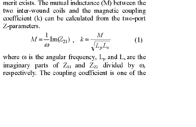
If it was a two-port structure, the mutual inductance would be imag(Z12)/omega.
For a four port structure am I correct to assume that the mutual inductance would be imag(Z14)/omega.
Hi fmdepassos,
It depends what's going on in your structure. How are the two inductors arranged into a four-port network?
Probably not!

I have attached a screenshot of how the ports are arranged. I can calculate the inductance and quality factor of both inductors by using S(1,1), S(2,2), S(1,2), S(2,1) for the primary and S(3,3), S(4,4), S(3,4), S(4,3) for the secundary.
However, for the coupling factor k (=M/sqrt(Ls*Lp)) I would need to calculate M, which is my main problem!
thank you for your help!
Here is how I calculate L and Q for both the primary and secondary

I think you can convert s-parameters to z-parameters then calculate M, k and the others.
10 to 20 percent losses is often quoted as the expected amount through a transformer. Try various coupling factors and see what results you get. Start with .99 which is near ideal, and decline. Just a few points later the losses are obvious. Very soon you're at 10% reduction of voltage, which leads to 10% less Amperes, making 19% less watts.
The L and Q curves don't look plausible. I wonder how you chose the S parameter reference plane and if you de-embed the transformer component?
Why do you say they don't look plausible? Because of the high quality factor? take into account that I am simulating this with a 9-metal 65nm technology using metal 9 (thick metal) and metal 8. Therefore I am far away from the substrate. That is the reason why I can achieve such good quality factors.
Regarding the reference plane, the ports are default from ADS, the reference impedance is 50Ohm.
I don't get your question about de-embeding. You use de-embeding techniques when you are measuring components in order to remove the effects of the PADs, probes, cables, etc.
I am simulating the transformer and not measuring it.
Thank you
The shapes looks rather typical for RFIC inductors over lossy silicon substrate.
For easier calculation mutual inductance, I would reduce this from 4-port to 2-port parameters.
I agree with you that the Q curves look rather typical!
Is there any kind of equation for that 4-port to 2-port parameter transformation, or can you do it in the ADS simulation?
Thank you
Excuse my ignorance, how do you get increasing L over frequency? That's not really inductance?
4-port parameters are required to model parasitic common mode impedance of a transformer. As the intended Ls and Lp parameter extraction is abstracting from any parasitic parameters beside losses, connecting the transformer as 2-port doesn't necessarily give worse results, I think.
Frank, that's from the parallel C between turns (not here for single turns) and from the shunt path (Cox + Csub||Rsub). For the effective series L in differential configuration, you then get this reponse.
Some more examples for such curved here:
http://muehlhaus.com/support/ads-app...uctor-em-ports
I meant to use 2-port parameters for calculating the mutual inductance only. For use of the S-parameters in the circuit, I would also prefer the full 4-port data.
I would do it in ADS circuit simulation.
Sorry for the (maybe) ignorant question: But if I simulate the component with 4-ports, does ADS has some transformation technique?
Or you mean you would do the ADS simulation with 2-ports? If you would do the simulation with only 2-ports, how would you calculate the inductance and Q of both primary and secondary?
Thank you so much for the help,
Fabio
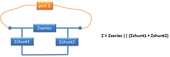
You can simply place the 4-port EM model (or S4P result) in a schematic and wire it for 2 ports (primary/secondary).
Z11 and Z22 is the impedance with the other side open (I=0), we then get L1 and L2.
1/Y11 and 1/Y22 is the impedance with the other side shorted (V=0), we then get (L1-M) in series with M||(L2-M) and (L2-M) in series with M||(L1-M).

Thanks Volker, your paper confirms my doubt that what we extract as effective (or should we better say apparent?) inductance from S parameters isn't the real inductance of a coil. I understand that we can nevertheless use the extracted inductance value to calculate e.g. the resonance frequency in a particular circuit configuration, e.g. differential operation.
But what is the conclusion for effective mutual inductance? We can extend your elaborated equivalent circuit to two coupled inductors with threefold number of elements and try to identify all with the full 4-port data. The effective mutual inductance seen in a specific circuit will however depend on the primary and secondary termination impedance.