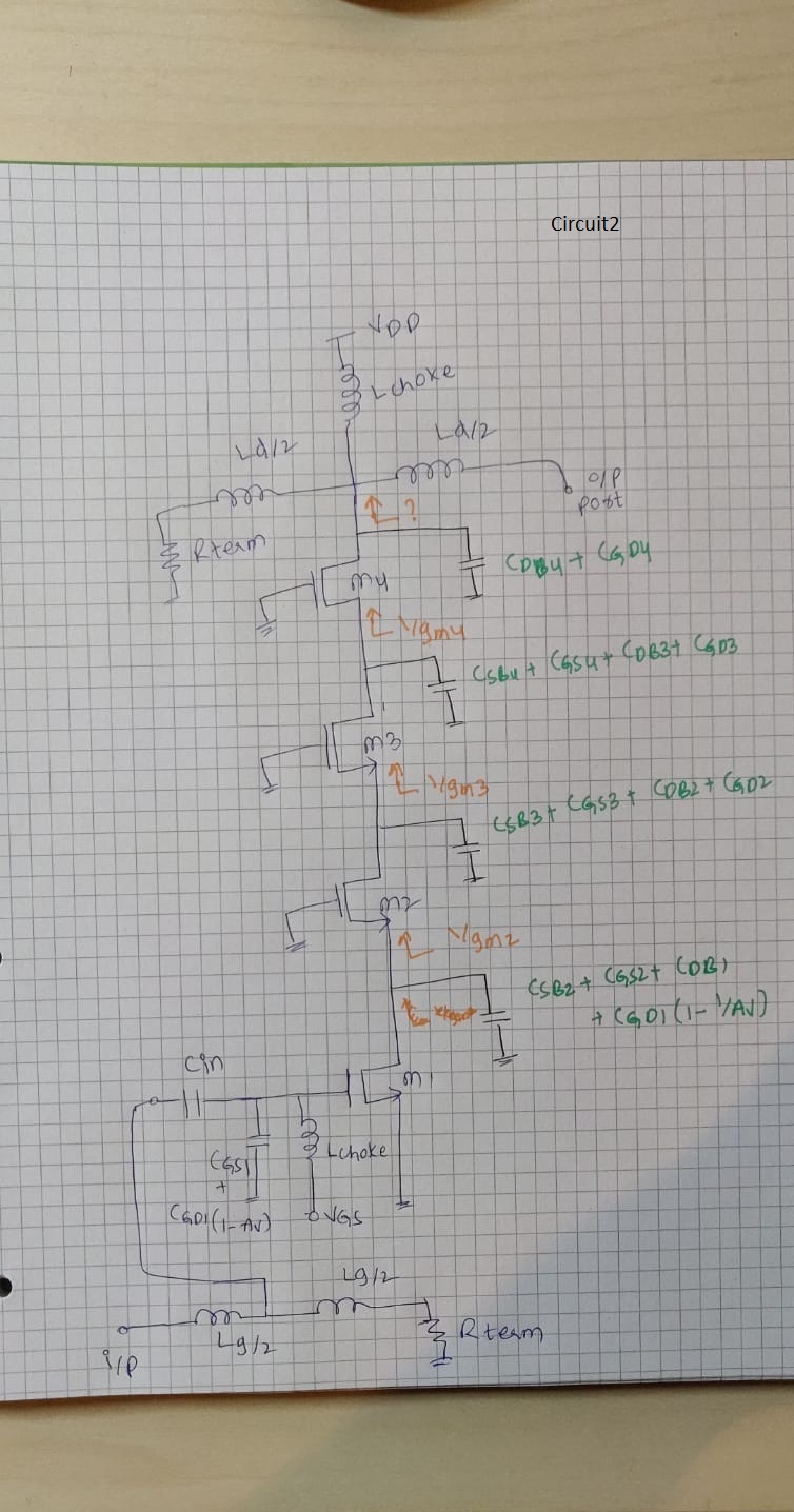
How to calculate bandwidth for this circuit, including lower and higher cut off freq
1. Is it correct, the resistance at nodes I marked as 1/gm?
2.How would I find the bandwidth from these pole frequencies (for both circuits)?
3. The input pole give me lower cutoff frequency and output pole give me higher cutoff frequency?
4.Can I already now without actually plugging in the actual values which are dominant poles?

Your schematics have a number of LC loops, and capacitors which can be switched in and out of the network. It looks as though components are able to resonate, and interact unpredictably, with other capacitors or inductors. Is that your intention?
But doesn't this look like a stacked power amplifier? Do we need to care about open loop stability of a power amplifier? If we can get rid of the feedforward impedance, then for passive terminations, shouldn't the amplifier be unconditionally stable? Because its a cascode structure, I would not expect s12 to be too large anyway normally.
Yes, there are schematics on the internet which resemble your circuits. My observations are general since I'm not familiar with their operation.
Wherever your circuit has a series LC or tank LC, it creates a center frequency. It may act as a bandpass or bandstop depending on the path of a signal. The chance of resonating is reduced if resistance is in the loop, either ohmic or transistor. High output resistance tends to increase Q. Cascode structure is associated with high impedance.
Q also depends on L:C ratio. To find the proper L:C ratio you need to consider how much current flows in the network. Then you can get sufficient voltage swings from the network, as long as you have a certain amount of current available to drive it.
This works if small resistance is in neighboring components such as transistors.
Yes, RC capacitor filters can be used in that way. The aim is to customize rolloff curves so they both conduct in your desired frequency range.
Either the resistance must be matched to a given capacitor value, or the capacitor needs to be chosen so it matches neighboring resistances. Resistance is hard to determine when transistors are in the path. It implies that several capacitor values need to be tried.
True, I didn't connect gate capacitors. Then how do we call this structure, cascode or stack? So if I dont connect those gate capacitors what changes would be there in performance parameters?
Electronics Tutorial about Frequency Response of Amplifiers and Filters and the ... but with a varying frequency such as those found in amplifier and filter circuits. ... So from this we are able to determine at a glance the voltage gain (in dB) for any ... a circuit operates at in between its upper and lower cut-off frequency points.