Energy harvest circuit questions

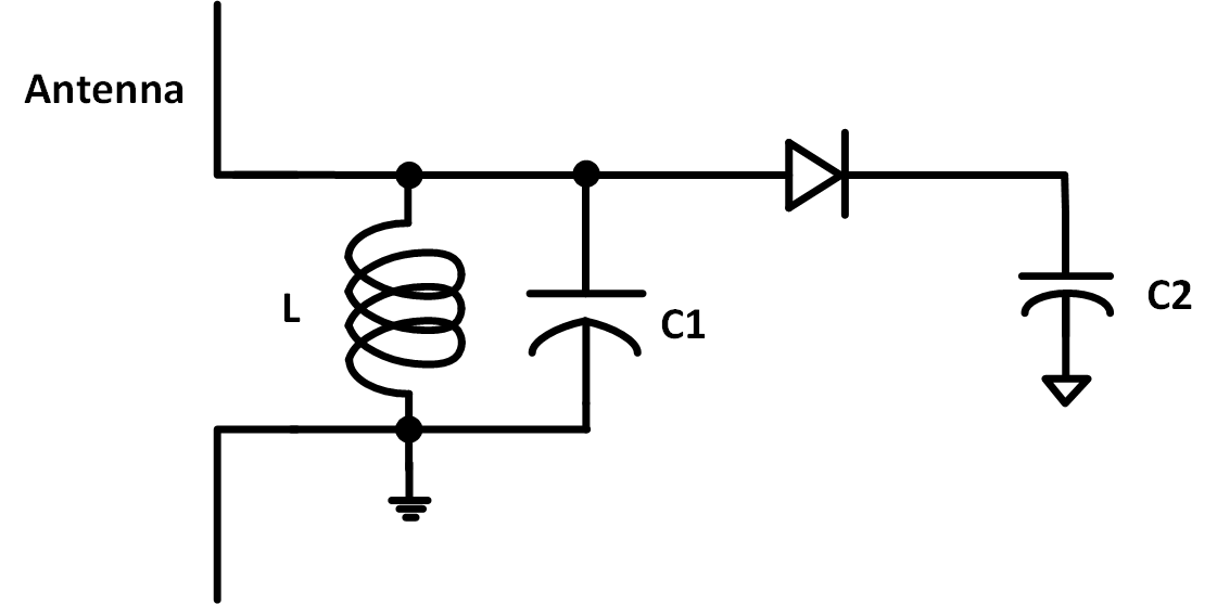
I have several questions about energy harvest circuit as shown in the above figure.
1. How is the " radiation signal" in the air converts to the voltage or current signal along the antenna?
2. Whether the capacitor C1 should add?
3. If the rf signal is 1GHz, what is the value of inductor and C1, or just the inductor value if C1 should be removed.
Thank you.
1. L/C1 are a resonant circuit, they selectively pick up one frequency of EM waves. The diode rectifies it and C2 acts like a reservoir to store the rectified DC voltage.
2. Without C1. the resonant frequency will be higher and decided by the properties of L.
3. there are no fixed values, they work in combination. The formula is " f=1/(2 * pi * sqrt(L * C)) " where f is in Hz, L is in Henries and C is in Farads.
Do not expect to get much power from this - if you are very close to a powerful source of radio emissions you might get a few mW.
Construction is critical at that frequency.
Brian.
Your schematic resembles an old-fashioned 'crystal' radio receiver. It draws its power from the radio broadcast itself. No other power supply is needed. It can drive headphones if they are high impedance type.
Crystal receiver at 1GHz ?
Brian.
Ah-hum, well, you never know who's putting out a strong signal on the airwaves at what frequency these days. It would be interesting to tune the entire spectrum, just to see which band yields the most energy for us to harvest. It might even turn out to be ambient mains hum in the walls.
I can guess it's not easy to construct a 1 GHz tuning circuit from scratch. However, starting with the crystal set, we can look at the specs (values & dimensions) for its components (antenna, inductor, capacitor), to deliver greatest sensitivity. Then scale those specs to suit the band we're interested in harvesting.
Wikipedia has an article about unpowered radio receivers ('crystal radio'). It says:
en.wikipedia.org/wiki/Crystal_radio
Assume an antenna stretched along the electric field of the signal. For simplicity, consider the length to be lambda/4. In that case, when the peak of the electric field (consider a sine wave) is at one end, the other end is at a zero field.
Electric field is associated with a potential; thus the two ends of the antenna will see a potential difference.
Can this antenna extract much energy from the EM field? The answer is: it depends.
The LC circuit attached to the antenna has a characteristic frequency of resonance. At that frequency, the circuit can extract maximum energy from the EM radiation field.
The signal strength must be more than the noise present in the antenna. The noise figure is frequency dependent and the antenna can be tuned by changing LC values to different frequencies.
Remember that all diodes have a forward drop and a reverse leakage; they will not see signal below a certain level (strength).
For energy harvesting, you will need a large antenna that covers a large part of the electric field. Basically each antenna corresponds to a voltage source but above the ambient noise level.
To put the energy harvesting in perspective Shanmei, There is a 5kW transmitter about 4Km away from me here transmitting on 880KHz. With a 50m long wire antenna and a good Earth connection I can get about 5uA detector current to flow using the circuit you showed. There simply isn't enough RF energy around to make it worth harvesting unless you are very close to a very strong signal source.
Brian.
