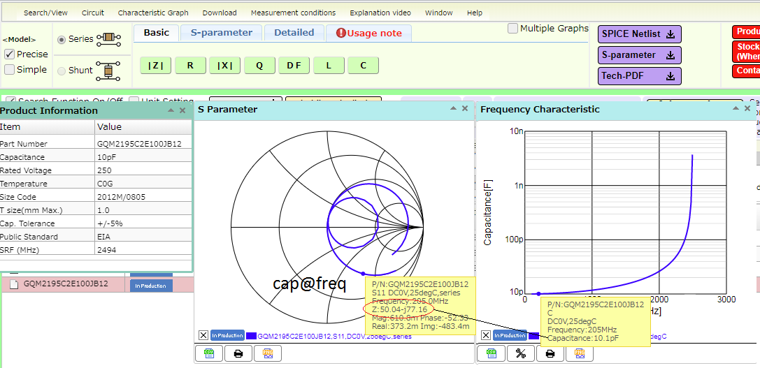
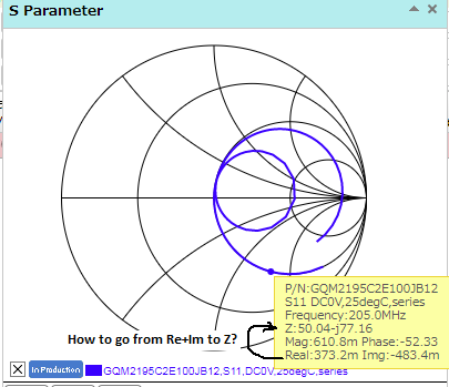
Calculate Capacitance Value from Smith Chart
Using GQM2195C2E100JB12
https://www.allaboutcircuits.com/too...ce-calculator/
Z = - jX
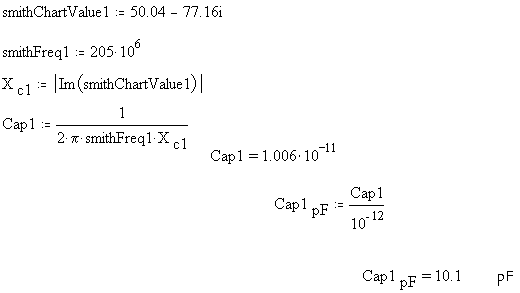
Z=-j77.16
So my impedance is 77.16 Ohm? Do I use this as the reactance (Xc)?
The smith chart for that cap shows you that at 205MHz it is 10pF ( 77 ohm ) and 50 ohm resistive ...
I see the real part (50Ohm) and the impedance in the imaginary part (77 Ohm).
Where/How did you see 10pF from the R+jX values on the Smith Chart? (of course I'm assuming the yellow window calculating everything for us is not always there).
the Smith chart is for a specific 10pF cap, that is clue #1, it is not explicitly shown on the Smith chart, but the 77 ohm at 205MHz gives you 10pF, presumably at very high freq the series L would reduce this figure ....
Not in all cases. There is a difference due to a phase change. The calculation needs to be fine-tuned by drawing parallelogram angles as shown in textbooks.
he reactive part is 77.16 ohms, this is the sum of the Xc & XL, at 205MHz it is basically all capacitive so yes = Xc
When there is negligible ohmic resistance, it's true that the capacitive reactance formula tells the impedance.
However if the resistor value is increased, it changes the situation so that C needs to be adjusted to a different value.
respectfully - even if there is loads of resistance as there is here - 50 ohm in fact - the Smith chart tells you the reactive impedance AND the resistive impedance hence 50-j77 ohm ...
Alright, after reading everyone's input, this is what I get.
Thank you!
Why do you confuse people if you don't understand the Smith Chart, and how to read it?
The original question was clear: 50.04 -j77.16
It was a simple question that nobody could explain clearly. I'm sorry you were confused.
chiques, my comment was for BradtheRad and his comment. He missed that you specified the proper complex value.
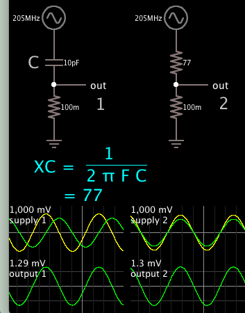
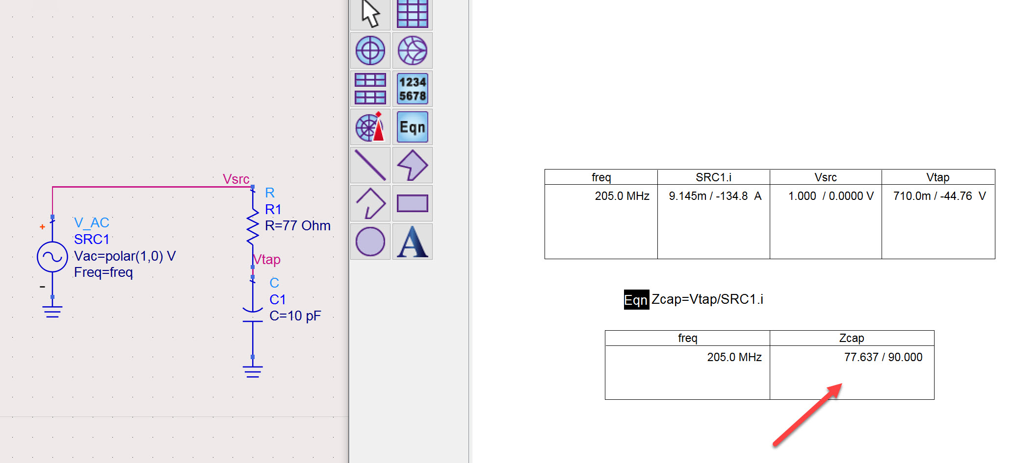
Here's the second half of my simulation. I increased ohmic resistance to 77 ohms, to see if
capacitive impedance still indicates 77 ohms according to the raw XC formula.
We expect it should create a twin 77/77 divider. We expect it to halve the 1V AC source. It does not. (It appears to be 0.5 multiplied by the square root of 2.)
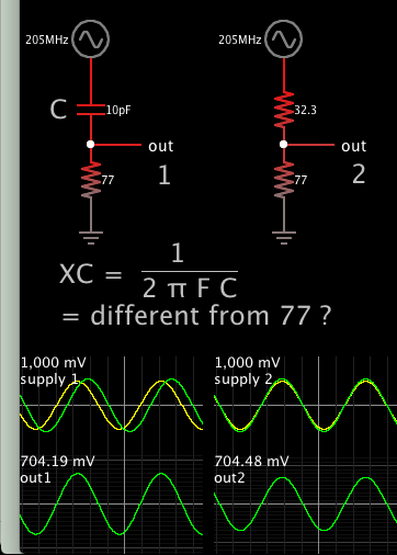
At right, the upper resistor was adjusted so output amplitudes match. The upper resistor needs to be 32.3 ohms, which tells us that's the effective impedance of the capacitor.
It's not expected when we see that the only variables are Farads and frequency in the XC formula.
No. Impedance is capacitor voltage divided by capacitor current, and then we get 77 Ohm from your experiment.
Yes, it would all be simpler if I'd seen only the calculator at the 'allaboutcircuits.com' webpage (post #2).
1/(2 ∏ f C)
The XC formula would be sufficient and I'd be happy to leave it at that.
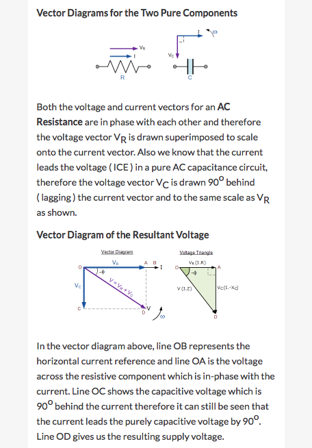
In addition however is a formula which complicates things: √(R^2 + XC^2). This is where the phasor diagrams (parallelogram angles) come in. And the capacitive impedance appears to take on a new value.
Example, this site (with screenshot):
http://www.electronics-tutorials.ws/...pacitance.html
Are you new to the concept of complex impedance? In the original post, there is a proper specification of complex impedance (real part from 50 Ohm termination, imaginary part from capacitor) so I'm a bit confused what you are trying to discuss (or show) here.
This is related to this post
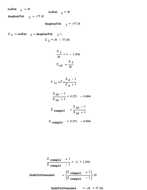
What is the formula/steps to convert from the (Real + Imaginary) value to the Z?
The complex value is (0.37-j.48) and the Z is 50-j77.16
Disregard, solved it.
Even if I were experienced at calculations with imaginary numbers and complex impedances, it's obvious I would need to learn more in order to account for the results of my Wheatstone bridge experiment (post #15). Isn't there more than meets the eye here?
Your simulation has the calculation of capacitor volts divided by capacitor current, to arrive at an impedance value. It's hard to argue with that. However, can we rely on the XC formula as our only guide? Nomenclature and formulas are a construct which we devise to explain real-life observations. What if we wish to calculate an ordinary RC filter? I think my simulation is hard to argue with too.
Of course we're careful to start with proper specifications for complex impedance and imaginary numbers. I'm not sure we can determine our Farad value exclusively from the XC formula, except if we factor in something else besides.