Re: Calculate Capacitance Value from Smith Chart
You expect the output voltage to be half the total voltage, because R and X are equal.
But that's wrong. The voltage divider gives R divided by total impedance, and that total impedance magnitude is sqrt(R2 + X2) in this case.
And yes, I pointed out that formula entering the picture in my post #17. So let's see if things are clearing up. I compared more variations to see what happens.
At left, equal voltages appear across the 10pF and 77 ohm. As you state, they are not 1/2 source voltage.
The other layouts are 2 series capacitors, or 2 series resistors. Voltages are 1/2 source voltage.
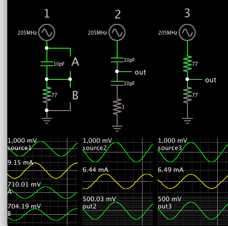
I believe the RC arrangement above yields 3 dB drop at the rolloff frequency. Output is 0.707 x source voltage, whether taken across C or R.
at the 3dB freq the volts reduce to 0.707 across the C only ....
No, Brad ist correct: the magnitude of R and X are equal in his left testcase, and current is equal, so indeed there is 0.7V across each of the components. But these voltages have a 90° phase offset, so that the total voltage magnitude is sqrt (0.7V2 +0.7V2) = 1V
apologies - I must be so used to dealing with L & C, certainly the freq most quoted is when R = 1/ ( 2 pi f C ) so the impedances are the same at that freq.
as the freq goes up the volts decrease across the C - I was stuck on that thought too