Question about single balanced mixer design
时间:04-04
整理:3721RD
点击:
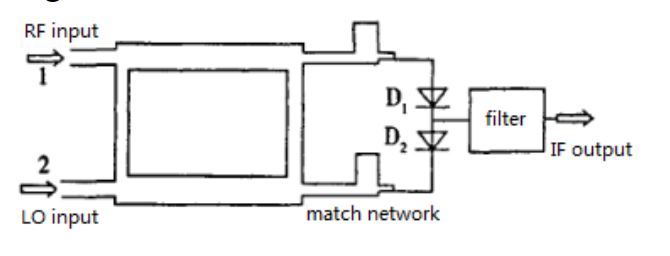
I'm trying to design a microstrip line based single balanced RF mixer using 90?° hybrid and 2 schottky diodes.
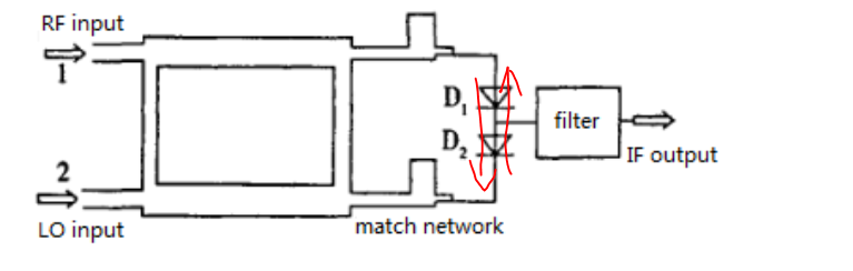
In this picture, is that matching network going to match the diodes to 50 ohms? I did it in my ADS simulation, but I found that the signal from one diode branch, which makes my isolation between RF an LO very bad. Just as the figure shows below.
How can I fix this problem?
This is a design I found from the internet. What does RFC do? And what do the networks after the diodes C,D and E do?
These problems confused me for a long time. It'll be really nice if someone here can help me with them
I see in picture 3 that there are answers to all your questions.
You may provide schematic for simulation you perform, including microstrip lines. Maybe problem is in schematic.
On the third image RFC is probably connection to ground for DC return path.
Look at figure Figure 5. "Ku Band Mixer using HSMS-8202" in: http://www.hp.woodshot.com/hprfhelp/...lit/an1136.pdf
In many modern microwave sensor designs C,D,E are made of single radial stub or quarterwave stub, because recieved RF frequency and LO frequency are relatively close, so single stub bandwidth is enough to short out RF and LO at the same time (for example 10GHz and 10.5GHz)