Monopole antenna is single ended or two terminal?
From the schematic I received from wireless engineer, I sometimes see the monopole antenna is two terminal, one connect to ground, and the other connect to the rx/tx of bandpass filter. While there are also cases that the monopole antenna is single ended with one terminal connect to the matching circuit and then to rx/tx of bandpass filter.
I do not understand the single ended case, if the antenna signal is high frequency voltage, means you need two terminal to receive the signal at the bandpass filter, one ground plus one signal. But in the case of single ended monopole antenna, I do not see the antenna has the other terminal connected to ground, or there is no other terminal of the antenna.
So, how is that possible to receive the antenna signal with single ended connection? I think the signal are totally floating, is it?
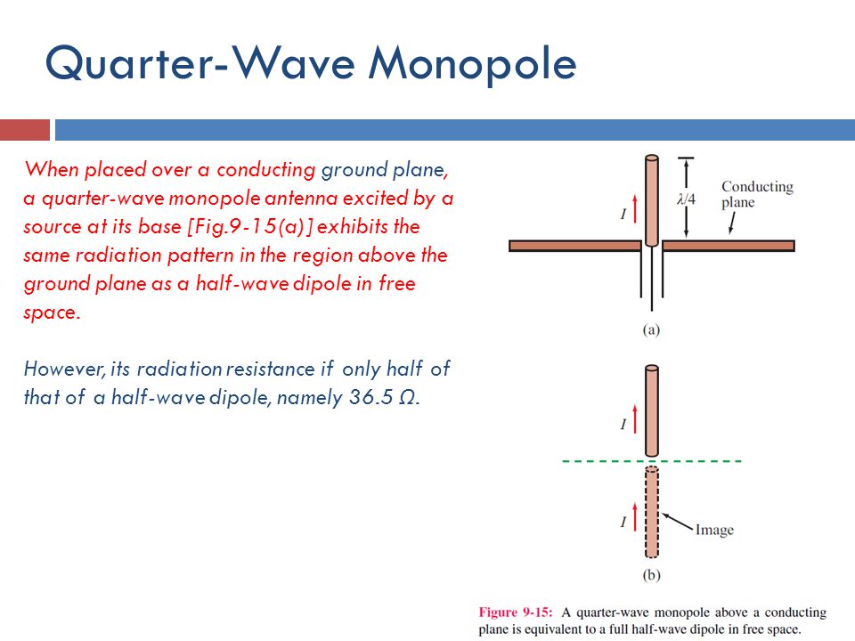
An isolated monopole doesn't exist, it always involves an (ideally infinite) ground plane. Practical monopoles are using a finite, in some cases rather small ground plane. The monopole turns into an asymmetrical dipole then.
The problem is that the whole circuit, including connected cables becomes part of the antenna. Any change to it affects the antenna characteristic.
Understand, so monopole antenna always pairs with a ground plane, though the size of the plane varies due to design limitations.
My question still exist, does the ground plane physically need to connect to by antenna by copper? or though cap? Or not? If yes, where is the connecting point in the antenna.
You just need to connect the monpole to the transmitter output or receiver input. As FvM says the ground is the rest of the antenna circuit, in effect it is already connected.
If you have an oscilloscope you can see the effect by touching the probe input, just the probe tip, not the ground. You are now a monopole antenna and the oscilloscope will show mains pick up that you are inducing into the circuit.
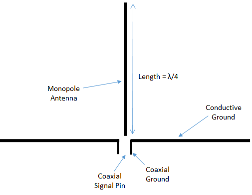
The monopole is connected to the signal pin of your transceiver/ feedline, the ground plane is connected to the ground pin of your transceiver/ feedline.
Even if your antenna symbol might have just one pin: physically, PCB ground provides the missing antenna ground. The monopole works with - and depends on - the PCB ground.
Thanks for the explanation.
However, I do see a case with PIFA antenna design, you have a feed point from the antenna connect to rx/tx, but you also have a short point near the feed point short the antenna to ground? In such case my understanding is that the whole antenna is short to ground, and then it can not be working as a antenna any more.
I know my understanding above is wrong, because in real case the design works, but how will that work? Where my understanding get wrong?
have a look at all the examples here ??.
https://www.bing.com/images/search?q...ne&FORM=HDRSC2
one example

so the coax core goes through the ground plane to the monopole and the braid of the coax connects to the ground plane

Conductors with dimensions in the order of wavelength are radiating structures. PIFA isn't shorted and antenna rod isn't floating, respectively they are only at low frequency.
That line to ground in PIFA is part of the design, with a well defined length at a well defined position on the radiator. This creates a shunt inductance for matching the antenna to 50 Ohm. Moving that shunt path changes antenna input impedance.
For regular monopole that is at 90° from the PCB ground plane (=less capacitive load of radiator than PIFA), the impedance is usually fine without that matching element.
