Amplifier Matching & Gain Circles
I currently have some problems with matching the MGA71543 LNA ( http://www.avagotech.com/pages/en/rf...hes/mga-71543/ ). To match a low noise amplifier, I usually plot the optimum noise match point and maximum gain (=s11* conjugate complex) match point, and then chose a matching network somewhere between both points to have a good noise match while still maintaining a decent S11.
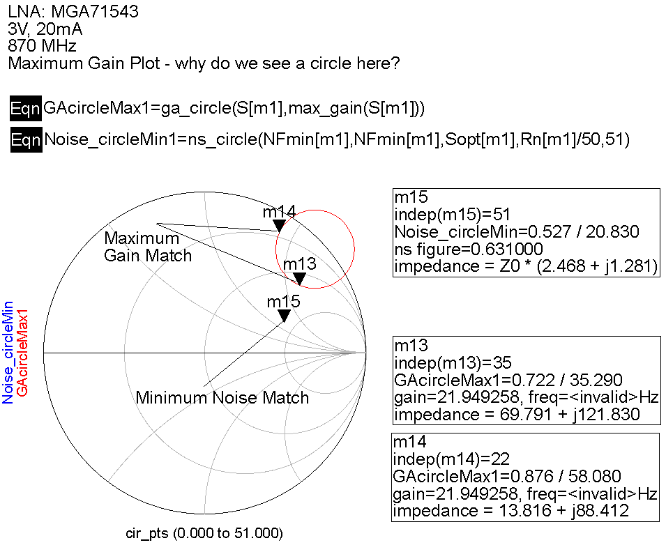
Though - with the MGA71543 I now have a strange result for plotting the maximum gain match. I expect a single point (= s11 conjugate complex), but it gives me a circle of (completely different) impedances which apparently all lead to the maximum possible gain!? (see attached picture)
Can this be correct? Why is MaxGain on a circle and not a single point?
mmm not sure what are u trying to plot with ADS here, but if you are trying to find the middle point between Gamma Opt@840 MHz (0.52 L 20°) and S11*@840 MHz (0.868 L 31°), this should be roughly:
0,691 L 24.755
Everything based on the 3V/20 mA sparameters.
For doing the match, I recommend the Smith V3.10 you can find here
http://www.fritz.dellsperger.net/
Afterwards you need to evaluate of course all into ADS considering the parasitics of the board/components.
Hope this helps.
English is not my mother tongue, probably I've been a bit unclear.
The graphic shows gamma_opt (marker 15) and the maximum gain match (the red circle, e.g. marker 13 and 14).
What confuses me is the red circle in the graphic I've posted. According to my simulations all input impedances on its line would give me the maximum gain of ~21,95dB. The gain can't be higher than this.
Usually I'd only expect a single point, which is s11*, to give me the maximum gain.
I've used exactly the same simulation setup for other amplifiers, and it always replied that specific s11* point within my simulation (so I suppose my simulation setup should be correct). Now here, when I implement the s2p file for the MGA71543, I get a circle of many different impedances, which are all resulting in maximum gain.
Now my question would be, can this circle be correct?
And if so, why is it a circle instead of a single point (s11*)?
difficult to know, I guess the stencil that ADS has for this under design guide, Amplifier, sparameters/NF/Gain/Stability/Circles groupd delay should bring some light.
check the gain/noise/stability circles tab after simulating.
alternatively you can send me your project and I can have a look at it.
cheers