Isolation in strip line couplers
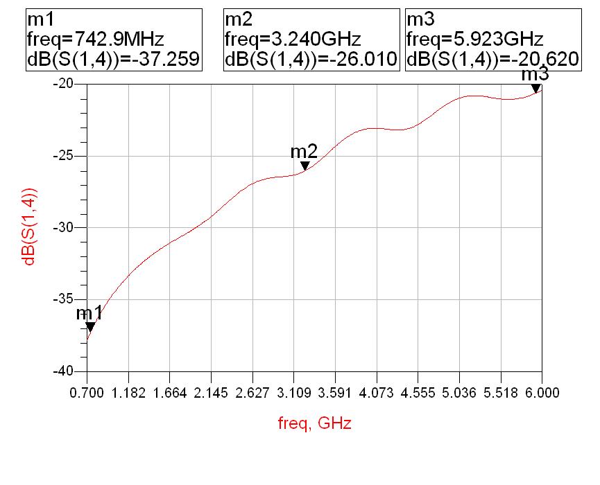
i have done wideband 15dB coupler upto 6GHz. the isolation S(1,4) is increasing curve from -37.83dB (@700MHz) to -20.5dB (@ 6GHz), the coupler was designed for 700-6000 MHz bandwidth. The other parameters return loss -24dB Min, insertion loss-0.6dB Max, coupling -15dB, flatness (± 0.8dB) of the coupler are ok.
how can we improve the isolation? if i calculate the directivity (isolation - Coupling) at 6GHz it will be 0dB or -0.5dB, is that oK?
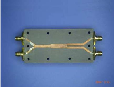
coupler is Strip line based design.
il is 0.6dB OK but flatness ± 0.8dB is confusing.
Also directivity at 6Ghz -20 minus -15 will be 5dB i do not know how u got 0dB
hi,
Flatness is 15±0.8dB in the overall frequency range from 700-6000MHz.
Directivity is 5dB @ 6000MHz not 0 dB, it was mistake that i have taken.
but a min of 10dB directivity is desirable, how do i improve that?
The design is Strip line edge coupling method.
Have you done the crossings?
like in telephones signal carrying conductors will be crossed to minimise the cross talk.
Better if you can share the design.
It's better to show your circuits.
Try to make the grounding better,especially the upper board.
hi,
it is basically Stripline technology with Edge coupling method
multi sections are used to get the broadband operation, sections are asymmetric.
width, W and separation between each section are calculated by even and odd mode impedances. W, S are optimized to get the proper coupling and other parameters.
but Isolation not met the specification, after varying these parameters.
Current design has no symetry. it has closer or tight coupling on one side and loose coupling on the other.
change to lose-tight-again loose model.
hi,
thats right, we can go for symmetrical structure with loose-tight-loose coupling. how does it improves the isolation there and why not here in asymmetrical design?
i guess,
by doing so, transitions will be matched better and freq will be further pushed away.
[/b]
when you try to approach symmetry, length of the outer coupled lined becomes half and hence gaining / extend in the freq
Hello,
Can you please guide me on how to get the values for w and s for every section of the coupler? Are there any calculators available for these?
Isolation strip couplers 相关文章:
- need ways to access the isolation effects of GND vias in PCB layout
- Parasitic Capacitance of the Isolation Resistor of a Wilkinson combiner
- surface current and isolation of antenna
- How to calculate ISOLATION VALUE for VCO output?
- simulating isolation between antenna using farfield of one antenna as source
- Isolation transformer with network analyser