How to calculate ISOLATION VALUE for VCO output?
I have found out experimentally,I need an isolation of better than 80dB between VCO
and mixer/modulator to avoid VCO frequency pulling to a great extent.
Is there a simple mathematical equation to find out before hand the isolation value required ?
It's totally depends on "Pulling Characteristics" and "Your Permissible Pulling Tolerance" of the VCO and there is no analytical expression to predict the Pulling Feature of a VCO to my knowledge.The output load changes create always a drift on the VCO frequency but this sensitivity can either be found by simulation ( bad choice ) or practical measurements ( good choice) and this is very depended on the VCO topology,OP,Nonlinear Element etc.But it has been observed that High-Q Resonator VCOs are less sensitive against Load variations due to strong Closed Loop Feedback mechanism.
take a sliding short circuit, put something like a 6 dB pad between it and the oscilator, and a 20 dB directional coupler. You see how many MHz the oscillator pulls +/- as you change the load impedance over all possible phases. Then you add 10 more db of attenuation, and see how much it pulls now. etc. If you know how much the frequency can pull in your system before you have errors...then you can calculate how much isolation you need.
One trick you can do is isolate the VCO from the load with other means. Like an opto-isolator will have 100 dB isolation if laid out properly. Some frequency multipliers have high reverse isolation, so run your oscillator at half the frequency and multiply by 2 before hitting the modulator. Digital dividers have extremeley high isolation, so run the vco at twice the frequency, and divide by two in a digital gate before hitting the modulator. There are other methods related to the modulator too.
The modulator/mixer should not be operating at same or integer multiple of locked VCO frequency to avoid VCO frequency pulling.
If modulation is to be done at 1500MHz, lock VCO at 1000MHz ,divide it by 2 makes it 500MHz and then multiply by 3 ,to make it 1500MHz.
So,by doing so VCO and modulator operating frequencies are not integer multiples,they are related by fraction 3/2 instead(i.e.1000MHzX3/2=1500MHz)
When VCO and modulator are not related directly they are highly isolated from each other,the system doesnot suffer from load pulling anymore,as
it doesnot experience any load change at its operating or multiple frequency.
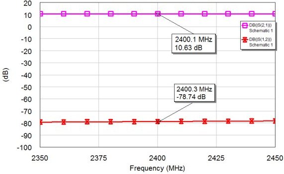
I was in a situation that I had to use a 2.4 GHz VCO (0dBm output) with very poor load pull performances.
I got almost 80dB isolation (and 10dB gain) using the following configuration: emitter follower (SiGe), 10dB pad attenuator, MMIC amplifier, emitter follower (SiGe).
Using the onboard 10dB pad attenuator after the first buffer gave better bandwidth performances (compared to situation when is placed just after the VCO).
- How to calculate bandwidth for this circuit, including lower and higher cut off freq
- Re: Calculate Capacitance Value from Smith Chart
- Calculate Capacitance Value from Smith Chart
- calculate mutual inductance of two close inductors from s parameters
- How to calculate the overall phase noise for a clock (frequency) network?
- I need to calculate the gate current of a pHEMT