Freescale MC56F8257数字信号控制器开发方案
steresis and configurable pullup device on all input pins
— Ability to generate interrupt with programmable rising or falling edge and software interrupt
— Configurable drive strength: 4 mA / 8 mA sink/source current
• JTAG/EOnCE debug programming interface for real-time debugging
IEEE 1149.1 Joint Test Action Group (JTAG) interface
EOnCE interface for real-time debugging
Power Saving Features
• Low-speed run, wait, and stop modes: as low as 781 Hz clock provided by OCCS and internal ROSC
• Large regulator standby mode available for reducing power consumption at low-speed mode
• Less than 30 μs typical wakeup time from stop modes
• Each peripheral can be individually disabled to save power
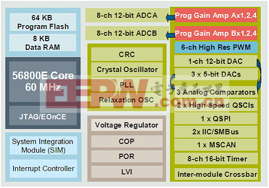
图1.MC56F825x方框图

图2.56800E核框图
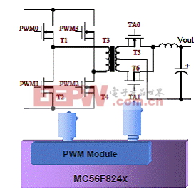
图3.MC56F824x相移电源转换器框图

图4.MC56F825x高性能PMSM伺服系统框图
TWR-56F8257: MC56F8257 Tower MCU模块
The MC56F8257 Tower MCU module (TWR-56F8257) is a cost-effective evaluation, demonstration and development board. The TWR-56F8257 can operate stand-alone or as the main control board in a Tower System with peripheral modules. It can also be used as the main control board with an APMOTOR56F8000E motor control board.
TWR-56F8257主要特性:
The following list summarizes the features of the TWR-56F8257:
• Tower-compatible microcontroller module
• Selectable power sources:
USB
Barrel connector
Motor control board
Tower elevator board
• Filtered power for VDDA and VSSA on the MC56F8257DSC
• MC56F8257 digital signal controller (DSC) in an 64 LQFP package
• Optional 8 MHz crystal circuit for the MC56F8257 DSC
• Nine LEDs controlled by the MC56F8257 DSC
• Motor control board connector for the APMOTOR56F8000E motor control board
• Auxiliary signal connector
• Four thermistors for single-ended or differential analog inputs to the MC56F8257 DSC
• CAN transceiver, header and termination
• Two push buttons for user input or interrupts to the MC56F8257 DSC
• Reset push button for the MC56F8257 DSC
• JTAG header for the MC56F8257 DSC with header to disconnect from OSBDM
• Headers to connect SCI signals to either USB bridge or elevator board
• Expansion via primary elevator connector
• MC9S08JM60 MCU with a 4 MHz crystal provides:
Open source debug (OSBDM) circuit
USB to SCI bridge
Header to select between OSBDM and USB to SCI bridge functions
Bootloader enable header
BDM header for the MC9S08JM60 MCU
Status and target power indicator LEDs
Control of semiconductor switch to enable power to board from USB
Voltage translators between 5V MC9S08JM60 MCU chip and 3.3V MC56F8257 DSC chip
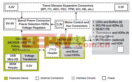
图5.TWR-56F8257框图

图6.TWR-56F8257板外形图

图7.TWR-56F8257板框图

图8.TWR-56F8257板电路图(1)

图9.TWR-56F8257板电路图(2)

图10.TWR-56F8257板电路图(7)

图11.TWR-56F8257板电路图(4)
TWR-56F8257板材料清单:


开发 方案 控制器 信号 MC56F8257 数字 Freescale 相关文章:
- 嵌入式软件设计中查找缺陷的几个技巧(03-06)
- 基于算法的DSP硬件结构分析(04-02)
- Windows CE下驱动程序开发基础(04-10)
- DSP+FPGA在高速高精运动控制器中的应用(05-17)
- 基于USB接口和DSP的飞机防滑刹车测试系统设计(05-19)
- 一种基于DSP平台的快速H.264编码算法的设计(05-19)