能源管理的小型便携式系统-Energy Management
battery life, and cost continues to justify additional voltages. Fortunately, the use of multi-output ICs minimizes the number of components needed to create these voltages. These ICs minimize the board area and the number of "glue" components required, while improving the system's low-load efficiency and other performance parameters.
With two ICs you can design a four-output power supply for hand-held organizers, computers, or data terminals (Figure 13). The output voltages are 5V for PCMCIA slots and analog circuitry, 3.3V for CPU and RAM, 12V for flash memory, and -17V for LCD backplane bias.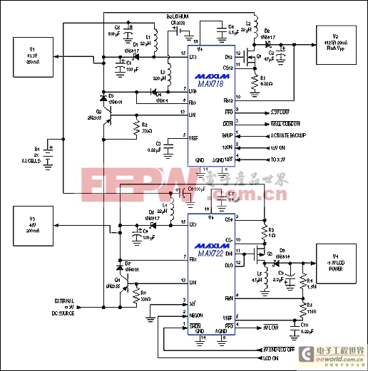
Figure 13. These two ICs perform a multitude of power-related tasks in a system powered by two AA cells. They generate four supply voltages, supervise the system power, control a lithium backup battery, and provide a switchover between battery and wall-adapter outputs.
A fifth regulator—a micropower boost circuit—is included for backup during battery replacement. It sits idle until the main battery dies or is removed, then supports the 3.3V rail by boosting the output of a lithium coin cell. The 5V and 3.3V main outputs are also overridden by pnp linear regulators (Q2 and Q4), which become active when you plug in an external unregulated dc supply. This action also unloads the main battery. The two ICs include several control and supervisory lines in addition to the four output voltages.
Simple Battery Charging
For small hand-held products, a lack of space and a limited budget often preclude sophisticated schemes for battery monitoring and charging. The goal in these cases is to squeeze the maximum performance from "bare bones" hardware. If available, though, CPU resources (combined with low-cost analog circuitry) offer a convenient means for charge control.
The 8-pin, step-down, switching regulator IC of Figure 14 is configured as a high-efficiency 1A current source, activated via a logic-level signal. The op amp (IC2) monitors the charging current with a sense resistor (R10) and applies feedback to the regulator chip. This "high side" current sensing lets the negative battery terminal connect directly to ground.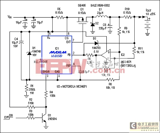
Figure 14. This 1A switch-mode current source supplies charging current to a grounded battery by sensing current on the "high side." An op amp senses the output current and supplies feedback to the dc-dc converter IC.
Switch-mode battery charging offers advantages, even for low-cost applications; it dissipates less power and makes full use of an ac adapter as a power source. Linear-regulator designs typically require wall cubes with twice the power rating, after you consider high- and low-amplitude extremes for the ac-line voltage. Linear designs also require heatsinks to implement fast charging.
The circuit shown generates a regulated current for charging a 3-cell battery. A 5.1V zener diode (D3) clamps the output at approximately 6.3V when the battery is removed. You can adjust for other battery voltages and currents by changing R5, R10, and D3. The operating-voltage range is 5V to 16V, but surges to 24V are allowed (with some output error).
If a fast charge is desired but no CPU resources are available, an "all-in-one" controller may solve the problem (Figure 15). IC1 is a low-cost NiCd charge controller operating in a low-loss, switch-mode charging configuration. The DRV pin drives a p-channel MOSFET (Q1) via the bipolar-transistor buffer Q1-Q2. The cell count (2 to 16), charge rate, and trickle-charge current are pin programmed via the IC's PGM0-PGM3 inputs.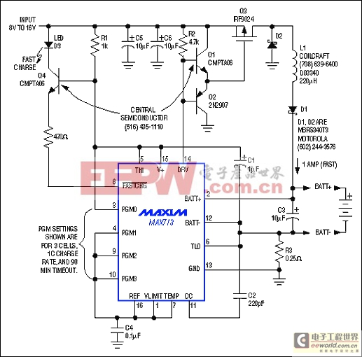
Figure 15. A low-cost battery-charge controller is the heart of a low-dissipation, fast-charge switch-mode circuit. When the battery is fully charged, the circuit shifts automatically to a C/16 trickle charge.
The circuit terminates a fast charge automatically by detecting a negative slope in the curve of battery voltage vs. time. For safety, it also provides an adjustable timeout as backup for terminating the charge. Note that NiMH batteries require termination at zero slope rather than negative slope. For NiMH batteries, replace the MAX713 with the pin-compatible MAX712.
Figure 15 accommodates nominal 12V inputs such as a car battery, and is therefore limited to charging batteries of six cells or less. As shown, the PGM0-PGM3 connections set the fast-charge rate at one ampere and the trickle-charge rate at 1/16 of that. The backup timer is set for 90 minutes.
模拟电源 电源管理 模拟器件 模拟电子 模拟 模拟电路 模拟芯片 德州仪器 放大器 ADI 相关文章:
- 采用数字电源还是模拟电源?(01-17)
- 模拟电源管理与数字电源管理(02-05)
- 数字电源正在超越模拟电源(03-19)
- 数字电源PK模拟电源(04-03)
- TI工程师现身说法:采用数字电源还是模拟电源?(10-10)
- 开关电源与模拟电源的分别(05-08)