能源管理的小型便携式系统-Energy Management
Boosting from Low-Cell-Count Batteries
The cell count for batteries in earlier-generation designs was high—not to provide more energy, but rather to allow generation of the system voltages with low-cost linear regulators (or even with no regulator at all). The latest generation of voltage-conversion ICs, on the other hand, lets you reduce the cell count while adding a minimum number of external parts. Usually, this extra cost is more than offset by the benefits of lower cell count: smaller size, less weight, and (sometimes) longer battery life. To illustrate, the 4.5Whrs of available energy in two AA cells exceeds the 3Whrs in a 6-cell, 9V alkaline battery by 50%, even though the two batteries are comparable in size and weight.
The step-up regulator of Figure 6a provides high, 88% efficiency for 2-cell and 1-cell inputs, and its high, 500kHz switching frequency enables the use of very small inductors. The IC's quiescent current is only 60μA at light or zero loads—an attractive feature for portable products whose supply voltage must remain active when the product is turned "off." As the product enters such an idle or suspend mode, load current falls to microamps and must not be dominated by current into the regulator IC. For equipment that truly shuts down, the IC provides a very low-current shutdown mode in which it draws less than 1μA.
One-Cell Regulators
It makes sense to operate from a 1-cell battery when size is of prime importance. Reasonable efficiency and cost is now possible when operating with inputs below one volt, so many hand-held applications have become new candidates for 1-cell operation. The switching frequency for low-cost ICs now approaches 1MHz, which permits the use of small magnetic components available from multiple sources. It's not unusual, therefore, for the dc-dc circuitry to occupy less space than the battery it replaced.
In Figure 6a, the addition of Q1 and Q2 within the dashed lines allows the regulator to start with lower input voltages and higher load currents. Q1 also disconnects the load and battery from each other during shutdown, and the on-chip comparator does not allow Q1 to turn on again until VOUT has risen to at least 3V. Figure 6b illustrates this circuit's loaded-start capability and its remarkably low typical start-up voltage (0.8V).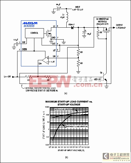
Figure 6. This low-power, CMOS step-up converter (a) generates 3.3V from 1-cell and 2-cell inputs. The optional load-disconnect circuitry (dashed lines) enables the circuit to start with inputs as low as 0.8V (b).
Figure 7 shows a low-parts-count step-up regulator that also starts under load and operates with inputs down to 0.8V. Its 500kHz switching frequency and adjustable peak coil current (set by RLIM) allows use of a tiny, low-cost surface-mount coil. The on-board active (synchronous) rectifier not only eliminates the external diode, it also enables the shutdown input to turn off the output completely—a useful feature not common in boost designs, and one that requires an external FET in Figure 6.
Figure 7. This single-IC boost converter has an internal synchronous rectifier. It maintains a regulated 3.3V output for inputs ranging from 1V to 6V.
The active rectifier and control circuitry in the IC of Figure 7 maintain regulation for inputs to 6.2V—an achievement which, if not of benefit in single-cell designs, may be useful elsewhere. The price for these improvements is higher quiescent current: 190μA for Figure 7 vs. 30μA for Figure 6.
Inductorless Conversion Suits Tight Spaces
Despite the advances made in inductor-based switching regulators, most
模拟电源 电源管理 模拟器件 模拟电子 模拟 模拟电路 模拟芯片 德州仪器 放大器 ADI 相关文章:
- 采用数字电源还是模拟电源?(01-17)
- 模拟电源管理与数字电源管理(02-05)
- 数字电源正在超越模拟电源(03-19)
- 数字电源PK模拟电源(04-03)
- TI工程师现身说法:采用数字电源还是模拟电源?(10-10)
- 开关电源与模拟电源的分别(05-08)