能源管理的小型便携式系统-Energy Management
rupt load changes. The power supply may idle at milliamp levels for most of the time, but to handle short RF transmissions or bursts of CPU activity it must also deliver high-amplitude currents for short intervals. Especially demanding is the RF transmitter in a GSM cellular telephone or other digital wireless system employing TDMA (time-division multiple access) techniques.
For cellular handsets, a desirable battery combination for minimal size and weight is three NiCd cells. The lowest-cost RF transmitters for this application operate at or near 6V. You might expect the expense of a switching regulator capable of delivering 2W at 6V to force the use of a five-cell battery. But, the high current is drawn only for 600μs or so at a 10% duty cycle, so a small step-up IC can supply the load.
In Figure 11, a reservoir capacitor powers both the TDMA logic and the RF circuitry. The capacitor supplies an average 200mA, but at 1.5A its output drop is less than 500mV after 577μs. A 1Ω resistor (R1) isolates the RF load from the dc-dc converter IC. While 4 x 470μF is certainly a lot of buffer capacitance in a hand-held device, the four surface-mount capacitors are far smaller and cheaper than two additional battery cells. The circuit's average power-conversion efficiency is 80%, and its quiescent supply current is only 60μA.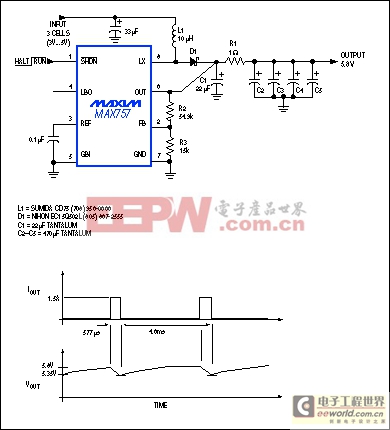
Figure 11. This circuit includes a large capacitive reservoir that supplies 1.5A transient loads in a GSM cellular telephone. The average load is only 200mA, so the 8-pin, surface-mount, boost-regulator IC requires no external MOSFET.
LCD Bias Supplies
The bias requirements for LCD panels in portable gear cover broad ranges of voltage and current, depending on the display's technology, screen size, and cost. Bias voltages may be positive or negative and as high as ±30V. The boost converter in Figure 12, for example, produces an output range of 20V to 30V, adjusted either by digital control or by an external potentiometer. This circuit's high switching frequency and adjustable inductor-current limit enable the use of small surface-mount inductors and output-filter capacitors. For loads below 10mA, for instance, the Murata-Erie LQH4 coil shown is only 2.6mm high.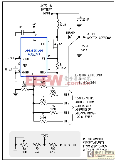
Figure 12. This circuit produces a bias (contrast) voltage for LCD panels that can be adjusted either with a potentiometer or digitally with a 4-bit homemade D/A converter.
Note that the potentiometer's configuration is not arbitrary (see the optional circuit in Figure 12). Connecting the pot between FB and ground (rather than FB and VOUT) ensures that an open or noisy pot wiper will produce a low output voltage rather than a maximum (and possibly destructive) output. Moreover, connecting the pot and its wiper to ground minimizes the trace area at FB; if you swap R8 and R9 the VOUT noise will likely increase.
In 2- or 3-cell applications you can optimize efficiency by biasing the IC from 5V (if available) instead of the battery voltage. The inductor still draws current from the battery, but higher voltage at the chip's V+ pin improves efficiency by providing more gate drive to Q1, which lowers its on-resistance. On the other hand, if battery voltage exceeds 5V then V+ should connect directly to the battery. VOUT can be adjusted by a 4-bit, 3.3V CMOS digital code or by the optional potentiometer, as shown.
Multiple Supply Voltages
Many portable designs require more than one supply voltage. Even as IC manufacturers add to the list of functions that can be powered from standard 3.3V and 5V levels, the need to optimize performance, weight,
模拟电源 电源管理 模拟器件 模拟电子 模拟 模拟电路 模拟芯片 德州仪器 放大器 ADI 相关文章:
- 采用数字电源还是模拟电源?(01-17)
- 模拟电源管理与数字电源管理(02-05)
- 数字电源正在超越模拟电源(03-19)
- 数字电源PK模拟电源(04-03)
- TI工程师现身说法:采用数字电源还是模拟电源?(10-10)
- 开关电源与模拟电源的分别(05-08)