能源管理的小型便携式系统-Energy Management
Three Cells to 3.3V
The circuit of Figure 3 employs the same principles as that of Figure 2, but adds battery-backup capability. It also foregoes the external FET for a lower-current internal one. Separate coils for L1 and L2 (vs. a single transformer) allow the use of a 22μH coil for each of multiple versions of the circuit—such as you would need in a product that required power supplies of 3.3V, 5V, 12V, and 30V, for example. The input-voltage range is 3V to 13V.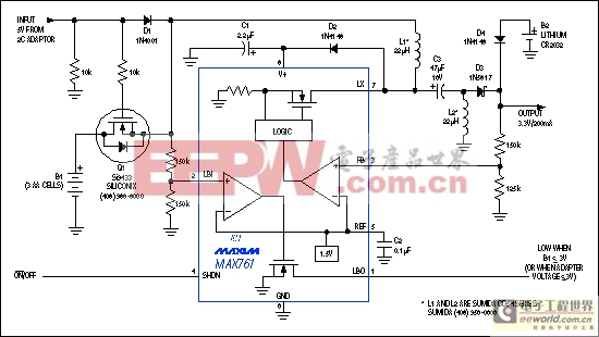
Figure 3. This low-current step-up/step-down regulator supplies 3.3V at 200mA. Q1 automatically disconnects the B1 battery when you connect an ac adapter, and a diode-OR circuit allows B2 to back-up the 3.3V output.
During normal operation, the ac adapter's 5V output powers the circuit and turns off Q1. Disconnecting the adapter removes 5V, turns on Q1, and allows the three AA cells to provide power. If the input voltage drops below 3.0V, a low-battery comparator in IC1 alerts the system by driving LBO low. And for backup, a diode-OR connection allows the optional lithium battery (coin cell B2) to maintain the 3.3V output. To simplify the switchover circuit from adapter to main battery, this design requires the ac adapter's 5V output to be somewhat regulated—to between 4V and 5.5V.
Low-Dropout, Step-Down Converter
Low-voltage logic, such as that powered from 3.3V, now enables the use of 4-cell inputs for simple step-down configurations that optimize efficiency and cost. For 3.3V outputs, the key specification is dropout voltage—the minimum allowable difference between VIN and VOUT. "End-of-life" voltage for the battery varies according to cell type and the product's pattern of use, but (for all but lithium batteries) it falls in the range of 0.8V to 1V per cell. As a result, it's not uncommon for 3.3V regulators to operate with input voltages as low as 3.6V.
The design of Figure 4 offers an uncomplicated means for delivering intermediate current loads at 3.3V from four cells. The IC drives a low-threshold p-channel MOSFET, and minimizes current-sense losses with a low current-sense voltage of 110mV. For best performance, the MOSFET on-resistance should be specified in conjunction with the circuit's lowest operating voltage—about 3.6V in this case.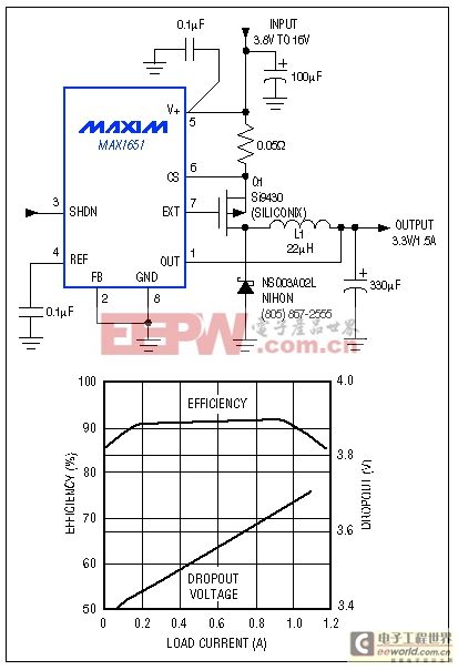
Figure 4. A low-dropout switch-mode controller and p-channel MOSFET supply 3.3V at 1.5A with inputs as low as 3.8V. Efficiency exceeds 90% for most of the operating range.
Linear Regulators
Still the lowest-cost approach for many step-down applications (short of no regulator at all) is linear regulation, provided its efficiency and battery-life limitations are acceptable, and its power dissipation at higher VIN is manageable.
For portable designs, even a simple linear regulator can provide some twists. As an example, dropout voltage (the low-VIN level at which output regulation is lost) should often be regarded as a part of normal operation rather than a fault. That is, to extend operating time it may be advisable to allow the regulator to fall out of regulation without shutting down. The regulator's behavior during dropout (especially its quiescent current) is important in these designs.
The simple linear regulator of Figure 5 offers exceptional dropout behavior with little effect on operating current. Essentially an 8-pin surface-mount package, it delivers more than 400mA. Because the internal pass element is a MOSFET instead of a bipolar transistor, the circuit's dropout voltage is nearly zero at light loads. And, its quiescent current does not rise as VIN approaches VOUT.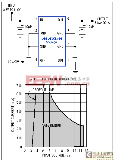
Figure 5. This combination of internal MOSFET pass transistor and high-power SO-8 package provides a linear regulator with low dropout, an operating current of 15μA, and an output capability of over 400mA.
This last characteristic is especially important for small portables whose steady-state load is no greater than 100μA. In such designs, the milliamp or more of quiescent-current rise (typical of a low-dropout regulator with bipolar pass transistor) accelerates the battery discharge at a time when the battery can least afford it: near the end. Typically, the IC in Figure 5 draws 15μA of operating current whether in or out of dropout.
模拟电源 电源管理 模拟器件 模拟电子 模拟 模拟电路 模拟芯片 德州仪器 放大器 ADI 相关文章:
- 采用数字电源还是模拟电源?(01-17)
- 模拟电源管理与数字电源管理(02-05)
- 数字电源正在超越模拟电源(03-19)
- 数字电源PK模拟电源(04-03)
- TI工程师现身说法:采用数字电源还是模拟电源?(10-10)
- 开关电源与模拟电源的分别(05-08)