[QUESTIONS] about oscillator on FM transmitter
时间:04-10
整理:3721RD
点击:
Dear all.
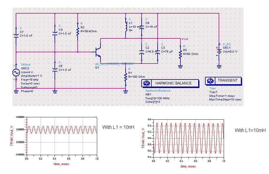
Refering to the image that i've uploaded
I"m designing an oscillator for my FM transmitter as a modulator. However, in the ADS simulation no matter what value that i change with the capacitor, i couldn't get the frequency that i wanted (100Mhz). Please tell me is there anything wrong about my design?
another question is about the inductor L1, as i varies the inductance, i obtained 2 different amplitude (the first one is less than 0.1V, the second one is around 0.5V). which one of these is suitable for me to sent into my VHF amplifier? it seems to me that the second one looks more promising.
another question, why when i change the inductor's value in the tank circuit, the frequency didn't change at all?
Please help, thanks in advance.
Alex
[/img]
Your values look very large in the diagram. L in mH and C in nF? At 100MHz you would expect L to be about 100nH and C in the 10's of pF
Also you are loading the circuit at Vout with a very low resistance which will kill the Q of the tank.
I did a simulation on a very similar circuit that you may look at
h**p://www.edaboard.com/viewtopic.php?t=189778&highlight=
I think it is an amplifier with sine wave as a input. Your sine wave is 15kHz. The reason that you get larger amplitude for larger L is the larger L is better for RFC. RFC is a device to block AC from the DC
For oscillator analysis you need an Oscillator Port (OscPort).
Search the ADS help to find what means this.
oscillator QUESTIONS transmitter 相关文章: