Help for my Collpits oscillator circuit
I use multisims and ADS applications for simulation. I use 2 types of transistors, BFP 420 and MPSH10.
and i build air core inductor with 4 turn and 1mm wire diameter for 12nh and 6 turn for 100nh
4 turn
6 turn
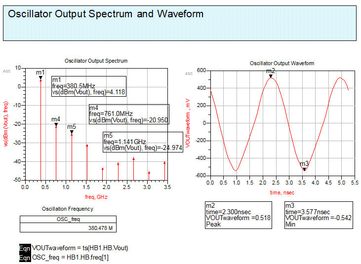
ADS simulation

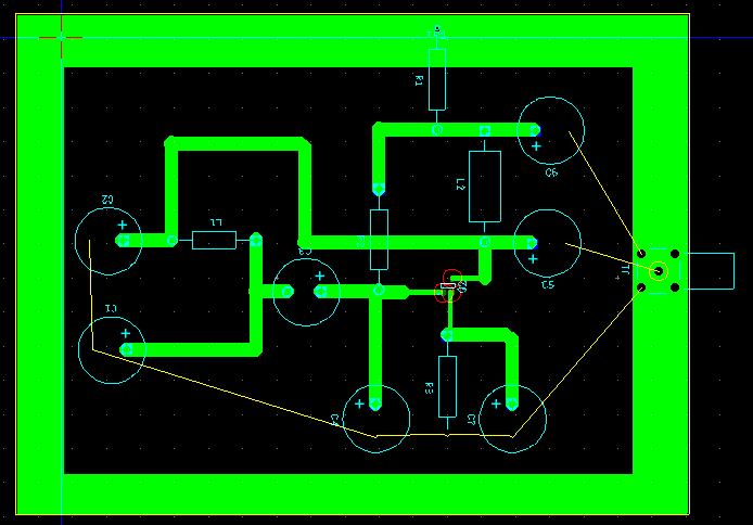
pcb layout (i forget to mirror)

PCB circuit
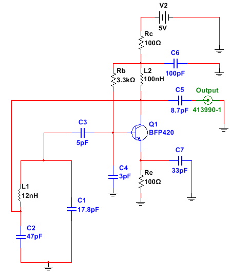
circuit

multisim simulation
PS
is it necessary for the amplifier buffer after the oscillator?
Here are some pointers regarding your project :
1) the BFP420 is a fairly low voltage device. So even working at your 5v might have damaged it.
2) the MPSH10 is higher voltage, but will not be able to give you enough gain at 380Mhz
3) the cap C4 is suspicious. Why is it there ? Instead you should maybe have a biasing resistor to ground. Rough calculation shows around 1.8K-2.2k should be good place to start. Your current scheme will probably drive the bjt into saturation.
4) Physically making very low value inductance is notoriously difficult. Your calculations do not seem entirely correct. In addition your PCB has very loose wiring - for high frequencies you MUST keep wiring length as close to ZERO as possible, unless you are using the trace itself. Note that a straight 10mm length of 1mm wire has L ~ 6nH, and a single 5mm diameter loop of 1mm wire has L~6nH. In your physical pcb circuit, just the loop formed by C1-L1-C2 would contribute a an additional 'stray' inductance of the order of upto 20nH or more. Stray capacitances are easier to control.
5) for decent bypass, use a larger value of C7 - like 470pF or more.
6) your base coupling capacitor C3 appears almost in parallel to the tank cap C1. So you have to minimise that, or factor into your calculations.
I suggest you experiment with your circuit config for lower frequencies (i.e. higher values of L) until you get more experience.
The problem is your layout..
It's too bad for an oscillator.Components should be SMD, the distances between the components must be short as much possible.
You should use high quality SMD components, pay attention to Transmission Lines etc..
You'd better research practical samples..You have to simulate your oscillator with its layout together ( Momentum+Co-simulation) because it will change too much thing..
Also, an oscillator in simulations is not obliged to oscillate..Oscillator design is a kind of "cut-and-try"..
Hi,
Spectrum analysers have 50 Ohm input impedance. Your simulations didn't contain it I think. Probably the measurement device overloaded your circuit and of course other mentioned reasons above can cause this issue.
Even with a 50 ohm termination the output should show SOME signal if it's working. A buffer is ALWAYS a good idea to ensure following stages don't load/ corrupt the signal. Since you get NO signal, I suggest you study my points and try to follow them
I disagree. If the open-loop gain is smaller than 0dB of the oscillator with the 50 Ohm load it simply won't give any signal. I mean if gain less than 0dB at the resonance frequency.
Good thing then that gain is NOT less than 0dB. If it was, it would not matter what the load is - even100k would be irrelevant.
So why disagree about these two unrelated issues?
1) but in the datasheet listed 2 absolute rating VCE, which one is used as a parameter for design? or maybe i used 2v 20mA?
2)on the datasheet listed Ft 650 MHz, can the transistor still generate gain?
3) if you use a resistor to ground, does the type of biasing change? like using a type of biasing voltage divider. or just replace C4 with a resistor? do you mean 1.8K-2.2k is Rb resistor?
4) ok i will try to use manufacture inductor, i bought 12nh inductor from coilcraft (https://www.mouser.co.id/ProductDeta...2uE6gMq6SrI%3D
6) is there a formula for calculating capacitive coupling? the reference that I read from Chris Bowick RF deisgn only explained the coupling, did not explain the calculation design
i design for vce 1.5 volt and ic 17.3mA, is that would be damage the transistor if i give 5 volt?
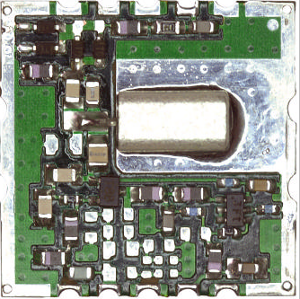
Look at this layout, does it look like to yours ?

the layout is just too open - which is not helping - your gnd plane is not a gnd plane, use blank pcb ( full copper sheet ) and solder every thing above this - then you will be able to do very short connections to a real gnd plane - keep the wires short on all your components... - by the way - couldn't see the "12nH" choke in the build pic ...? missing ? also 4V max if you don't want to cook the xtor ...
This seems correct.
It's better to choose device with fT much more than operating frequency. 5x - 10x if possible. MPSH10 is less than 2x
Also - your mouser inductor is 100nH, whereas your critical LC tank inductor is 12nH
Easypeasy post#11 suggests using 'ugly construction' style - which is a great idea! But much harder to do if using SMD's
