problem getting RF power into a coil
1- What might be the poblem here?
2- How much coil connections quality can affect current flow?
3- Any other idea how can I mak peak to peak voltage to decrease and current inside the coil to increase?
4- Am I in the right track?
I guess it all depends on how much you trust the auto-matcher readout! If it says there is very little reflected power, then the incident power has to be going somewhere. That means it is either going into the coil, or is heating up the electrical connections to the coil. If you look at the coil, does it look like someone took a welding torch to the connections between the wires and the coil? If so, clean them off well and reconnect tightly.
It has been a long while since I worked with one of these types of setups, but we used to use a flourescent bulb near the coil to see just how much power was radiating. The brighter the bulb, the more power going to it. I have used smaller neon bulbs to check microwave field strengths inside of a chamber--not sure if they would work down at 13 MHz, but it might be worth a try. You can put the neon bulb at the end of a non conducting stick (like fiberglass) and probe around.
I would also make sure there is no arcing going on anywhere near the coil, as that will consume all the power. Look for black carbon arc tracks leading away from the coil.
The voltage and power calculation seems wrong. The coil current can be expected to be mostly reactive for a correctly matched inductive coupler. If the generator is actually sourcing 2 kW power, the V*I product will be much higher than 2000.
On the generator I went up to 2000W and checked returned power is almost zero on the generator. What is the correct current and wattage inside the coil?
On the automatcher I can see peak to peak voltage is 2000 V. No trace of arc and no extra heat on the contacts. Everything seems very normal except there is no stronge plasma as I was expected. This type of coil I used usually used in ICP mass instruments but in ICP mass frequency is least 27 MHZ. I can see after a few minutes both generator and coil cooling waters geting warm. I have separate 10 liter tanks closed loop water cooling recirculating circuits. One cools Rf generator and the other one cools coil and automatcher. What I suspect is connecting the coil return end to the automatcher chassis. I think I should connect coil return end to the ground end of the coil inside the automatcher. I can't think of anything else. Automatcher also shows both load capacitor and tune capacitor are at their ends if this helps to diagnose the problem.
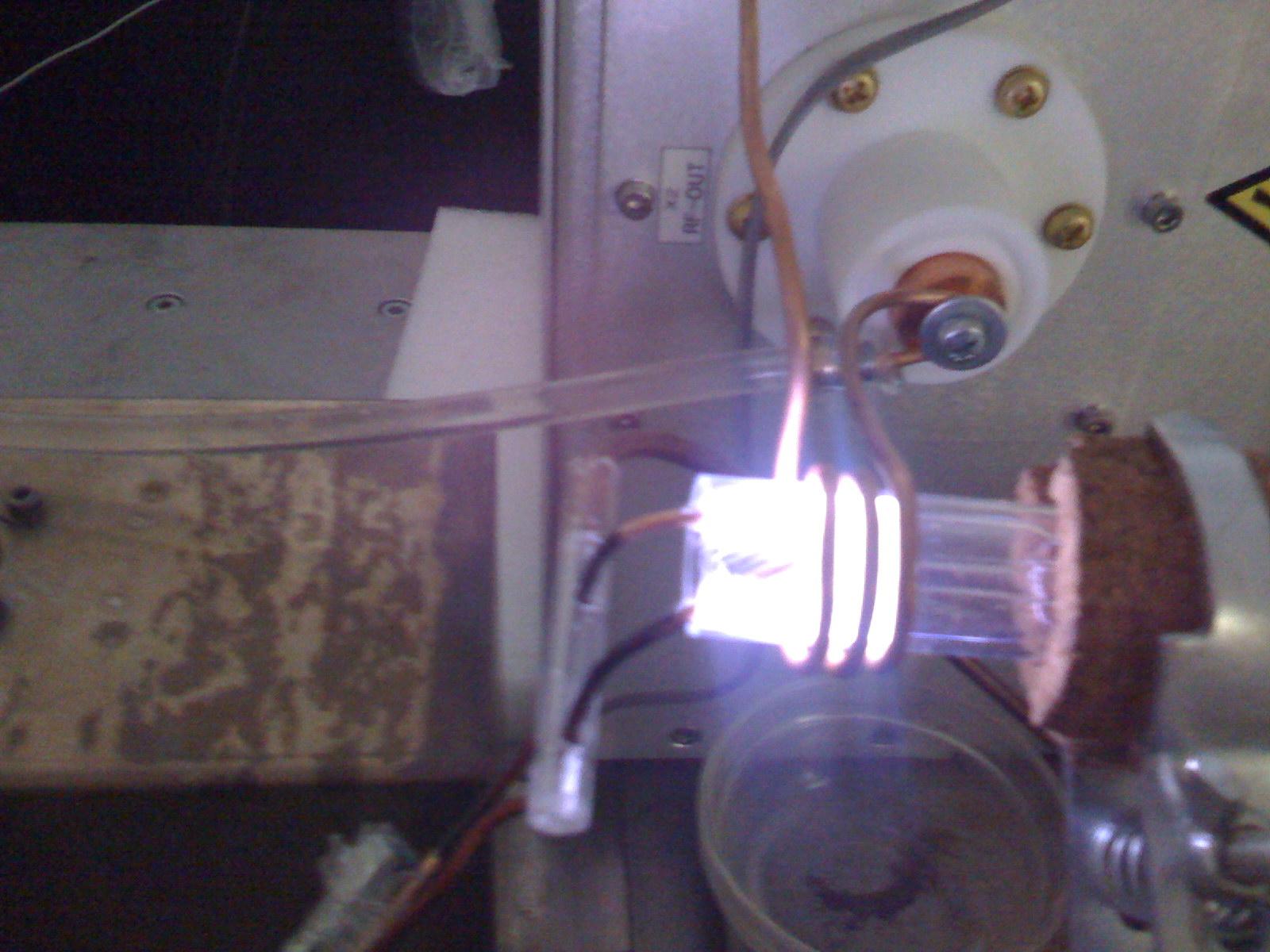
I have attached the photo of the turned on torch showing coil connection to automatcher output (ground connection is not shown) and two leads of spark generating device went inside of the quartz torch from the front.
I don't know, where the generator power is absorbed, possibly in the coil or partly in the automatcher cicrcuit (if the VSWR measurement is correct).
Generally, you should consider, that the H field of the coil doesn't directly exitate the plasma rather than the induced E field. If I understand right, it's considerably lower for same coil current at 13.56 MHz than at 27 MHz. So you have to apply either a higher current or use a larger coil for 13.56 MHz operation.
At the moment I have zero reflected power. Is that possible to have impedance matching in two points? I mean one with high voltage+low current and one with low voltage+high current?
If so I might be able to match impedance with tap increase or decrease of the coil inside the match box and see if I can get another matching point with higher current?