Why there are splited lobes in H-plane for probe feed patch.
I am now designing probe feed patch array antenna.
But I saw two equal-splited lobes in H-plane, which are not what what I want.
Can anyone help me explaining this?
Thanks in advance.
A figure would be helpfull.
I am trying to build a scan beam array with probe feed patch antenna as radiators. I found that the pattern in E-plane is just OK, but in H-plane it came as two splited lobes.
Can anyone explain this to me.
Null at boresight.
Please check the current distribution in the H-plane.
Hi Kohi,
Thanks for your suggestion. Can you explain how the current distribution should look like in H plane.
Thanks
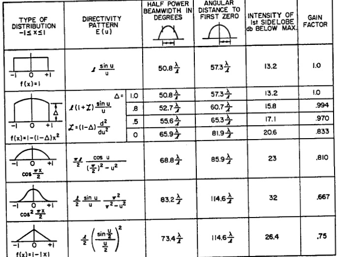
The H-plane should look like the E-plane.
Peak intensity in the centre and tapers towards the edge.
Hi Kohi,
I really appreciate if you can illustrate it.
Thanks.
Hi Kohi,
Thank you very much. It really helps.
Can I ask where you got the table. Is it from a book? Maybe I can refer to the book for more information.