PCB 100Mhz ANTENNA with ground back plane Measure surround dielectric
Sensor needs to be a PCB probe for low cost easy implementation. Exploring antenna or capacitance proprieties at 100MHz from pcb strips or some pcb design. Source inject 100MHz and need to measure reflected signal with detector.
See pictures of ideia concept:
PCB prototype:
How will work a antenna with a back ground spaced at 2mm (PCB tickness) at 100MHz. How will it patern radiation? I only need range 10cm-20cm for surround dielectric measure.
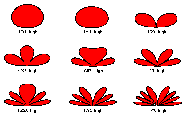
I've seen some patterns with backgrond near at some wavelenght " how act antenas from ground" :

What will happen if ground is 2mm away at 100MHz?
Reflected signal will change with surrounding dielectric, so this value will be measured with a AD8307 logaritmic detector -75dBm to 17dBm range.
Oscillator will be a LTC6905 (up to 170MHz clock generator low cost simple to implement) but output is a square wave with 3Vpp. How can I match this output to this kind of "anntena" ? Square wave from LTC6905 needs to be smooth correct?
Any welp is welcome.
There is some development at UHF frequency for sand dielectric measure.
http://autoid.mit.edu/current-resear...d-sensing-tabs
http://www.hizook.com/blog/2015/08/1...nternet-things
and also a product based on UHF measuring
http://www.farsens.com/en/products/hydro-h401
but this one uses resistive principle. I need isolated PCB non contact to media.
This were capacitive sensors I tested ,one of them designed by myself uses a Zigbee outputing 4MHz for sampling capacitance of sensor. but now go to antenna principles pcb. So need new design.
Hi Vitoa,
Your sensor is not really an antenna. There is not radiation involved in your sensor, but impedance changes.
The radiation patterns you show are in far field in free space.
You sensor would act a a very poor radiator even if free space (very low radiation resistance), a bit because it is short with respect to 1/4 of wavelength but mainly because close to a ground plane it acts like an open short transmission line (a capacitor), not an antenna.
Regards
Z
Hi, the impendance of sensor will change so there will be some difference at detector.
The sensor acts as a capacitor, but in series with resistor and drived by oscillator ,a voltage divider is used to the input of detector. Impedance of capacitor will change with surrounding dielectric. I want to measure this differences.
But previous antenna design is not the best. The antenna could not radiate because all back ground. Antenna is unpredictable inside soil. I go back switch to capacitive probe and use return loss bridge technic to get measure.
Check this thread https://www.edaboard.com/thread353626.html
This is the new design:

New design for the sensor "Return loss bridge at 100MHz usind AD8307 RSSI power meter" starts here at post #23
https://www.edaboard.com/thread35336...ml#post1512594
