Microstrip Line impedance matching network required at 1825MHz using ADS momentum
I need micro strip line matching network for 1825MHz , designed in ADS MOMENTUM. Schematic files are in attachment .
I want to match (0.5-j*0.6) ohm to 50 Ohm. I have tried many times but design does not work on prototype board. There might be some discontinuity issues which i have tried to solve using MSTEP component.
I want the matching network which is designed in
LDMOS POWER AMPLIFIER DESIGN (Mustafa Konca) - Academia.edu
I think there is a bug/problem around MSTEP component.I have tried to create a layout with MSTEP component in your project file but I couldn't..
Create this component manually...
THANKS for reply
I have designed matching network for transistors which are stable at the desired 1800MHz frequency. My LDMOS PD20015 is unstable at 1800MHz . To stable it, series resistors are added at the input side as shown in the attached file. Now the question is that how can i simulate the matching network plus resistors pads in the momentum. In case of stable LDMOS input port is place directly to the first matching element/largest patch. Where is the proper location for the input port in case of unstable LDMOS.
It's not a bug. The "step" element has no layout. It only represents the electrical effect of a step in line width. You should use this when you cascade two line elements of different width in a circuit simulator.
Thanks,
What about stability resistor issue.
I don't want to run unknown *.exe files.
Can you upload the ADS project in the usual format (zap/zip)?
here is zip file
I cannot open your project in ADS 2009U1. I tried renaming the directory with _prj suffix, but it is not recognized as a valid project.
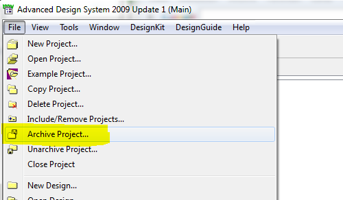
Please create a *.zap archive with File > Archive Project
It is ads2011 project
Ok, that works.
I think that your issue is caused by the use of the MLIN elements for the stub. The model behind the MLIN is not made for such very short segments of extremely wide line. Also, the placement of the capacitor seems wrong to me. My proposal of how to model this more accurately is added to your project. Archived project is attached.
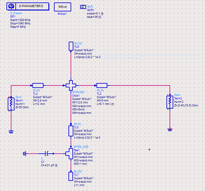
Amendment: TL5 should be 2mm shorter than shown in my screenshot/project. These 2mm are added by the MTEE and MLOC elements.
thanks.
I want to follow the following project. In this project same technique is used.
LDMOS POWER AMPLIFIER DESIGN (Mustafa Konca) - Academia.edu
You asked what the problem in your model might be, and I answered your question, based on the experience from working for these RF EDA companies since the early 90's. These circuit models are limited in accuracy, and you use them way outside the intended parameter range. I tried to show you a method that is still limited, but more accurate for your specific layout (open stub). The paper that you quote uses cascaded lines with different width, so there MLIN/MSTEP are the (only) way to go, although not accurate.
Which method is more accurate to follow.
how can i simulate the following schematic in momentum.
Use circuit simulation for initial design, but don't trust results. Use Momentum to verify the results from circuit simulation.
And for your specific layout, have a look at the ADS project with my modified version. That's not perfect, but more accurate than the initial version.
I would include the resistors as resistive sheets in Momentum. Draw the resistors on the resi layer and assign the proper ohm/square in the EM substrate dialog.
What is the method for resistive sheet? I need more explanation.
---------- Post added at 12:10 ---------- Previous post was at 12:00 ----------
I cant connect tfr model to other transmission lines
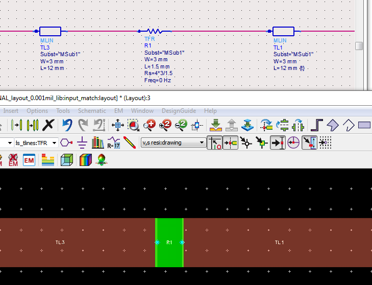
Go to layout and draw rectangles on the resi layer, which represent your resistors. Choose a size which matches the true physical size of your resistors. Set the ohm/square for the resistor layer so that you get the resistance.
If you prefer auto-generated layout, instead of drawing manually, you can use the TFR schematic element. In this case, you use one TFR for the tree parallel resistors.
How can i specify a 10 OHm resistor of 805 package?
---------- Post added at 12:25 ---------- Previous post was at 12:20 ----------
Kindly send this file.
That's your homework
My file with the 4 ohm TFR is attached.
Thanks for reply.
---------- Post added at 12:50 ---------- Previous post was at 12:43 ----------
The problem is that tfr resistor does not attach to the strip lines.
---------- Post added at 12:54 ---------- Previous post was at 12:50 ----------
I think i have some mistake in substrate modeling