RFI/EMI filter design
help me with design of active filters for >65dB atten at 30MHz in CM and 80dB in DM .
My switch mode converter 450watts generates noise at input source.
The passive double stage pie filters with Y caps are falling insufficient at 45dB .
There shall be 28VDC input from battery /rect. inputs ..
Any reference source books?
could you give more details about your questions? What is CM, and what is DM?
CM = Common Mode
DM = Differential Mode
vimalkhanna are you sure the interference is leaving on the DC wires alone and not between the AC and DC wires. Low frequency interference is often radiated with the source in the middle of a dipole formed from both input and output wires.
Brian.
here is an scheamatic diagram for EMI filter. I hope it will help you.
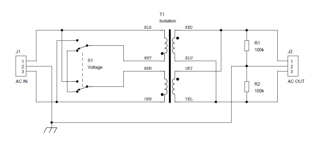
Have you meant to show a filter - or an isolation transformer?
T1 on the diagram says "isolation" and there are no capacitors indicated ... usually isolation is often done to isolate a circuit from direct mains connection for safety during trouble-shoot purposes such as on direct off-line powered switching power supplies.
Also, attenuation of >65 or 85 dB to noise will require more than just a single transformer, inter-winding capacitance can contribute to signal passing through a transformer too!
At attenuation value of > 60 dB (a power ratio of one million to one) attention to parts selection and layout are going to be critical. A DM (Differential Mode) attenuation is going to be especially difficult as moist inductors applied to a single line will not have the 'balancing' effect of a supply and return current and so the circuit magnetics will (or can) saturate and the actual 'effective' inductance value will decrease. That is why most EMI filters pass both supply and return wires through their ferrite cores, to balance the magnetizing currents against each other.
Jim
The series/parallel toriodal ferrites give the couplings from SMPS to battery. .
These inductors are PTFE coated .The caps are leadless multilayer ceramics SMDs to cater to no lead length antenna radiation and pickup.
The dual pie designs have y caps returned to flame ground.
The entire PCB has a mu-metal shield case enclosure for strong external magnetic radiations .
However ,from my switchmode converter PWM using 51995 ,,I still have more than 45dB noise injection to 28VDC battery ..
Await more ideas on what can be done .
vimalkhanna,
It would help to know what frequencies are still a problem and getting through, or around the filter. Then maybe an approach can be recommended (more shielding or different component layout and routing).
The EMI test lab should be using a "LISN" (Line Impedance Stabilization Network) after the power supply and before the product under test to present an impedance of approximately 50 Ohms to the 'noise' voltage the product under test (your SMPS) creates. This allows a common baseline to be established for measurements with lab and EMI compliance RF gear (spectrum analyzers and RFI/EMI receivers)
So, the question is, what frequencies are appearing either at the output of the LISN at the sample port (frequencies typically below 30 MHz) or what frequencies are being 'radiated' (typically above 30 MHz for tests in North America for FCC regulation compliance) as measured using the usual Log Periodic and Biconical (wideband) dipole antennas at the test range.
We recently went through the 'drill' of working to meet EMI/RFI compliance, including ETSI regulations, and we found out some of our boards were creating strong RF energy around 150 MHz (due to various clock rates on the board) and not due to just the power supply (SMPS) switching. We also had some extraneous RF leakage up around 2.3 and 2.6 GHz but that required attention to shielding of the RF power modules.
Jim
Tried too get the spectrum upto 100MHz but that shows marginally clean with a few strays pulsing up to 40-30dB peak ...
However , that is the polyscope limits.
Beyond this the overall noise jumps up ?Regret not having opportunity to go thru the RFI/emi DRILL ..
- Semi-rigid vs flexible cable for antenna feed
- Cellular telephone emissions locking-up electronic circuitry ?
- EMC Chamber need in EMC emissions test
- Antenna test using Semiconductor Device Analyzer B1500A Agilent
- small semi-rigid coax with air dielectric
- 2n3904 but with a larger Emitter-Base breakdown voltage