Re: RF Trace design for GSM module
Hi gentlemen,
I want to ask an interesting question:
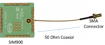
I want to solder "RG-178 50 Ohm coaxial cable" direclty to SIM900 module's antenna output pins and another part of cable soldered to SMA connector. In this way, i want to by-pass RF PCB trace design (impedence matching) process.
I saw similar to this trick on a GPS vehicle tracking PCB. On that PCB, GSM module has an antenna that is about 2-3 millimeters diameter coaxial cable (i don't know which model of coax) directly soldered to the module
Is this simple method a good solution? Any opinions
I dont know, how you intend to connect the other SIM900 pins, but soldering RG-178 or a similar small cable either directly to the SIM 900 pins or to a carrier PCB directly beneath the antenna pins should result in a good impedance matching. I would preferable use a crimped 50 ohm connector at the other cable end.
Some mobile phones are using a small semi rigid cable instead of micro strip for internal connection of RF output to achieve lower losses.