Equivalent circuit for a DIY coil
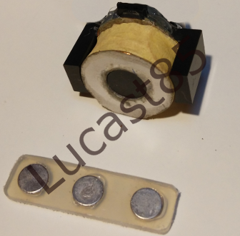
I recently built a coil with about 1500 winding of enameled wire copper, 0.2 mm of diameter. The coil was built using a DIY coil former and I use an ETD shaped core (N97 material).
This is the coil (and a set of three magnets):
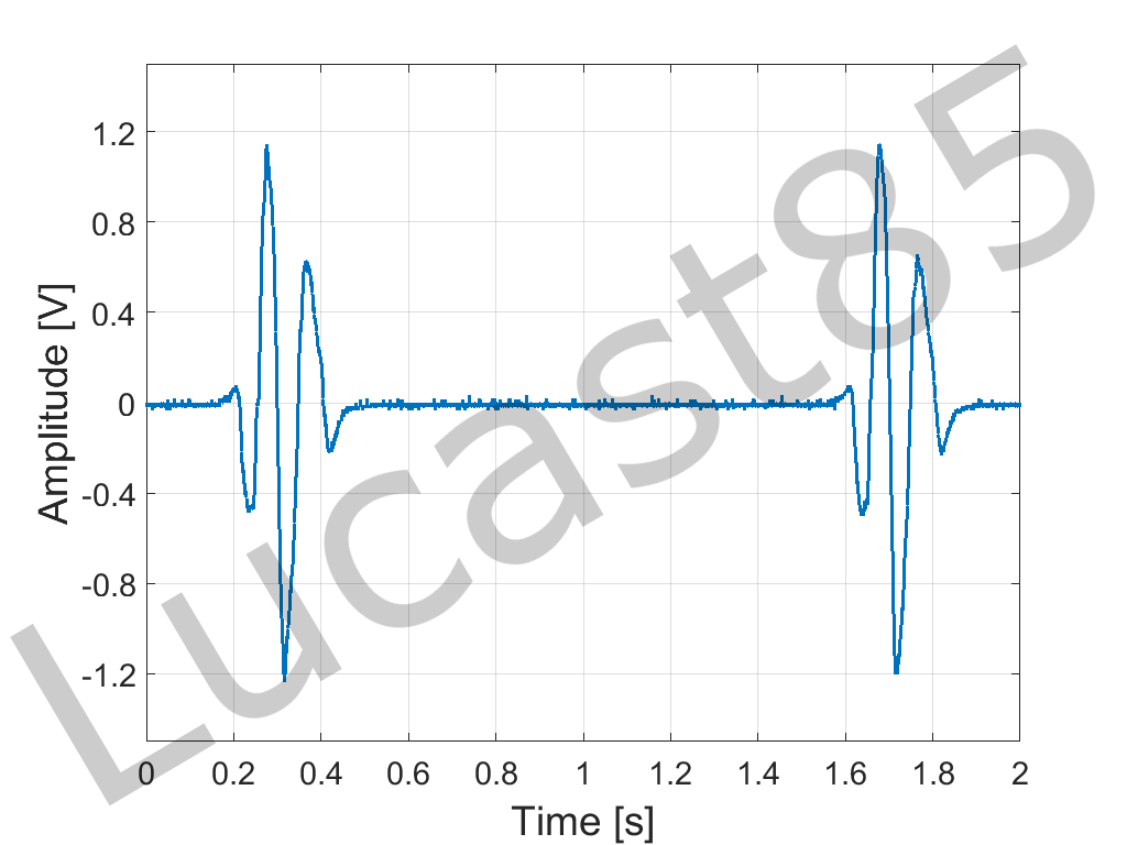
I did some experiments by passing some magnets close to the core and i measure the induced e.m.f. with an oscilloscope (1 Mohm probe). The waveform I measured was the following:
I hypothesize that the equivalent electrical circuit is the following:

in which the voltage Vs is the voltage measured by means of the oscilloscope with its 1 mohm probe and Rs is the inner resistance measured by means of a multimeter in DC.
In your opinion, what are the limit of the above electrical model? Obviously, Vs and Rs is the representation of the coil and RL could be the resistive load.
Could be a good representation of the system if the goal is to use it into a SPICE simulator during a transient analysis?
Thank you in advance for your opinion.
Coil inductance is more important than series resistance. But actually the equivalent circuit is mostly irrelevant with slow (100 ms scale) signals as shown in the post. For fast signals, winding capacitance (in combination with probe capacitance) matters, too.
Did you intentionally make a complex multi-pole magnet arrangement to get a respectively complex waveform? Or did you show the reaction of a single magnet?
yes, the blue waveform is the voltage measured with a multi-pole magnets arrangement. There was 3 magnets with opposite polarization (N-S-N) that passes close to the coil at certain speed.
I think the effect of the internal inductance and capacity of the coil are implicitly included into the blue waveform thus they don't have to be represented with discrete components into the model. It could be?
circuit Equivalent coil 相关文章:
- Help to find equivalent circuit model from .lib file obtained from hfss
- Assigning a circuit(Schematic) to IC in PIPRO, ADS
- Easiest to script circuit layout tools and electromagnetic simulators?
- Circuit input for EMC two capacitores 90 degree
- ADS Simulation of Circuit -Help
- Open Circuit impedance and Short Circuit impedance.