Parallel Trace Board
If anyone could share some design starting points for reading or tutorials, that would be great.
Not completely clear what you mean with a "parallel trace board". If you are talking about a PCB with multiple micro strip lines or strip lines, their transmission line parameters (Z0, td, dispersion and attenuation) become in fact essential for GHz frequency. The problem isn't about circumventing transmission line effects but to utilize it.
Hi, sorry for the lack of clarification. Yes, I am talking about a PCB with microstrip lines. Can you elaborate on what you mean?
You get more or less ideal transmission lines and have to use it in your circuit respectively, e.g. terminate with characteristic impedance.
10 GHz would typically use RF substrate (Rogers) for lower attenuation. You should give brief information about intended signal quality, either in time or frequency domain parameters.
Would embedded strip line be an option, too? Promises less dispersion and cross talk.
Thanks for the response. Sorry if this is a stupid question, but I'm still a little confused mainly about how to achieve certain lengths while maintaining monotonic insertion loss profiles. In my previous example, if I were to try and model a 3 inch trace, I would, from transmission line theory, expect to see resonance at 1GHz, as the wavelength of 1GHz wave is about 12 inches. This is more or less what I see when I try and model in HFSS. However, I've measured a few 3 inch traces in the lab and they all have very linear S21 profiles, and perhaps see resonance at very high frequencies (~10GHz), which goes against what I thought and see from simulation.
Ideally, I am trying to get something that exhibits as low insertion loss as possible while having as much far-end crosstalk as possible. This is sort of for study purposes, and I would like to develop various channels in-house to to see how much crosstalk and/or loss a given broadband receiver can handle. Right now, I am hoping for something with maybe 5-10dB loss at 10GHz and 15-20dB insertion loss at 20GHz.
You get transmission line resonance if load and source impedance are unmatched. GHz transmission are usually impedance matched at both ends.
Thanks for the response. Based on your explanation, does that mean I should only expect resonance at frequencies where the characteristic impedance is unmatched to 50 Ohms? I tried to draw some simple lines in a sim tool for a 6 inch pair of microstrip lines.
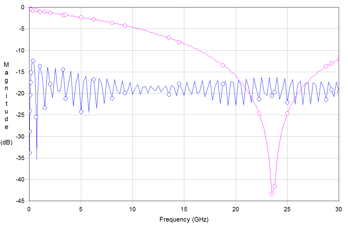
The pink curve is insertion loss (S31) whereas blue curve is return loss (S11). It seems like impedance is relatively matched across frequencies but there still seems to be some resonance at high frequencies (23.5GHz). Are there techniques to get rid of these high frequency nulls?
S11 ripple indicates that impedance matching isn't really good, may be one end is completely unmatched.
Attenuation is rather high, the transmission line doesn't seem to be usable beyond 10 GHz, in so far 25 GHz behavior is more a theorectical problem. Micro strips are non-ideal by nature, they have certain coupling to free space and respective dispersion. Depending on the exact design geometry, there may be also ground plane modes and other unwanted effects.
Referring to manufacturer data, insertion loss with dedicated RF substrate can be as low as 0.07 dB/inch @ 10 GHz (Rogers RO3003).
I like to use AWR's free TX-LINE calculator as a first step to estimate line parameters of coupled microstrip or stripline. Once I've got that, if have a copy of ANSYS's 2D solver, it's helpful for tweaking the result to be just what you're looking for. The last step, once you think you know what you've got, is full wave simulation in HFSS to get more accurate numbers. If line attenuation is important, be sure to include frequency-dependent dielectrics and metal loss.