Traces on PCB at 2.45 GHz
时间:03-29
整理:3721RD
点击:
Hi,
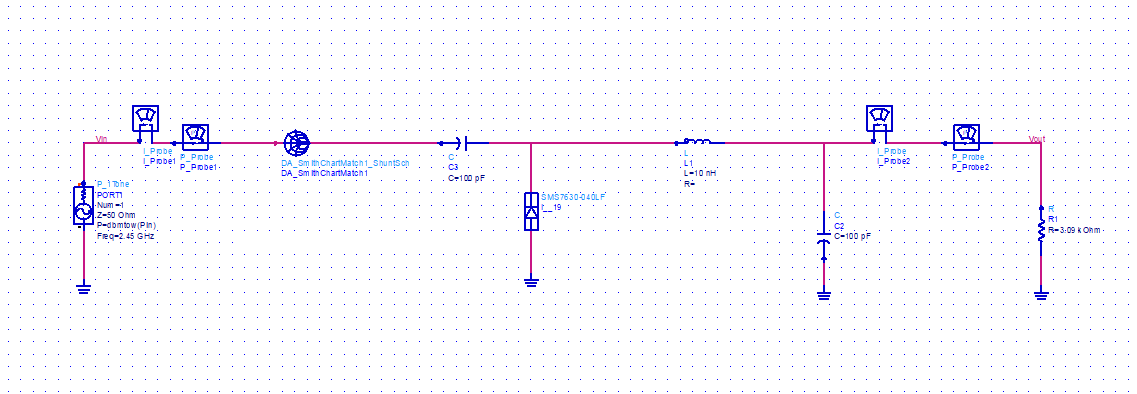
I'm studying this harverster circuit
I have a simple and newbie question, i know that i need to connect all these components with traces, but i know also that can't be arbitrarily, i need to calculate all traces to not affect the circuit behavior, but how can i do that? With quarter wave transformers? Can i use the line calc tool on ADS for this?
Thank you
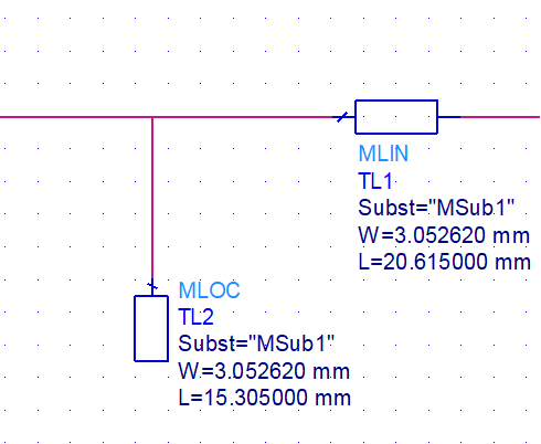
I did the calculation of the microstrip lines in ads line calc tool:
I want to insert another trace before my matching circuit, and don't change my matching frequency.
Thanks
I put 50 Ohms on Z0 and i get some Width (determines the impedance of the line), but for the length can i determine arbitrary? Or i should set an specific Electrical Length?
I'm studying this harverster circuit
I have a simple and newbie question, i know that i need to connect all these components with traces, but i know also that can't be arbitrarily, i need to calculate all traces to not affect the circuit behavior, but how can i do that? With quarter wave transformers? Can i use the line calc tool on ADS for this?
Thank you
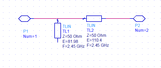
I think my question isn't clear, i used the smith chart tool on ADS to match the antenna with rectifier and i got this:
I did the calculation of the microstrip lines in ads line calc tool:
I want to insert another trace before my matching circuit, and don't change my matching frequency.
Thanks
Design the line impedance for your source impedance (50 Ohm).
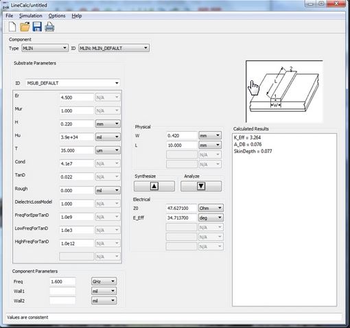
I put 50 Ohms on Z0 and i get some Width (determines the impedance of the line), but for the length can i determine arbitrary? Or i should set an specific Electrical Length?
Yes, any length is fine, because Zsource = Zline
栏目分类