Plane wave normal incidence on a Lossless dielectric in ONE Dimensional FDTD
I have one problem with dielectric interface in 1D fdtd by YEE method.
I have a plane wave that normally incident to an air-dielectric interface.
dielectric is lossless with permitivity of 20.
source is sinusoidal that excite domain from left side:
Ey(1) = source;
the problem is one dimensional.
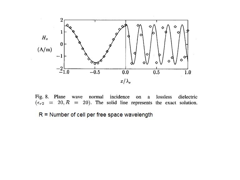
in the following figure:
"YEE solution" suffered from a complete phase reversal with respect to the "exact solution" after propagating only "one free space wavelength" inside the dense dielectric.
how?
in this example:
number of cell per wavelength is = 20
dielectric permitivity = 20
is there anyone who can give me a code that simulate this figure in one dimensional FDTD?

Hi ghasem_008,
It appears that your phase velocity in the dielectric is incorrect. Is the far right side absorbing?
hi PlanarMetamaterials
thank you for your attention
why phase velocity in dielectric is incorrect?
far right is absorbing finally , but in this case we dont need to absorbing boundary condition in the right side. because simulation time is choosed to wave dont reach to right boundary.
in fact in this figure , right side is in dielectric medium.
The phase velocity appears to be incorrect because the period of the wave in your solution does not match the period of the wave in the correct case. Since it's time domain, can you measure the speed?
what is the period of the wave in the correct case?
suppose:
the wavelength in free space is lambda_0.
so:
wavelength in dielectric is : lambda_0/sqrt(eps_r)
where:
eps_r : dielectric permitivity
I can measure the numerical velocity by "dispersion relation" in one dimensional.
can you write a one dimensional matlab code?
sqrt(20) ~= 4.47, looking at the figure that's pretty much correct for the solid line.
Your dots, on the other hand do about 4.8 wavelengths, which gives an e_r of about 23.
Have you ensured your permittivity value is correct?
yes i'm sure.
it's not very important that we have 4.8 or 4.5.
my problem is that i can not obtain phase difference about 180 degree between numerical and exact solution by FDTD code.
can you help me?
if I send my matlab code,can you correct it that result in this figure approximately?
That would cause your phase difference.
As another approach, your problem may be numerical accuracy. Try increasing the number of cells per wavelength from 20 up to 50 and see how the results change.
i changed it,but the result is not same as the paper.
in fact my answer is as following:
if we replace dielectric medium with free space (namely total domain is free space), numerical and physical wave will have 180 degree phase difference, approximately after propagating 160*lambda0.
now if we use from dielectric interface (same as the figure), this 180 degree phase difference will
occur after 160*lambda_d or 35*lambda0.
where:
lambda_d = wavelength in dielectric medium
lambda_0 = wavelength in free space medium
BUT, in the figure, 180 degree phase difference will occur after propagating only one free space wavelength inside the dielectric.
why?HOW?
Did it change at all?
Ruling out an incorrect dielectric constant and numerical inaccuracies, there's not much else I can think of without further information. Can you attach the MATLAB code? I can take a look, but I'm not too familiar with the method.
I sent it. please see your inbox.
thank you
I understand that what is the procedure.
exact solution is obtained by analytical expressions:
E(z,t) = E0*exp[w*t - k*z]
H(z,t) = H0*exp[w*t - k*z]
therefore, we have to compare FDTD result with analytical waveform.
NOW,my question:
can we use from E(z,t) = E0*exp[w*t - k*z] formula to plot exact E in time domain?
because before dielectric interface we have:
total field = incident field + reflected field
and after dielectric interface:
total field = transmitted field
BUT , reflection and transmission coefficients are frequency dependent,generally.
I have a sinusoidal source in FDTD.so can I use reflection and transmission coefficients in time domain?
Reflection should be taken into account by your code if its written properly. You can get the (in this case, frequency-indipendant) reflection coefficient from basic electromagnetics texts.
From your code, the fields are calculated as:
Hy(1:nz) = Hy(1:nz) - dt./mu(1:nz) .*(Ex(2:nz+1)-Ex(1:nz))/dz;
Ex(2:nz) = Ex(2:nz) - dt./eps(2:nz).*(Hy(2:nz)-Hy(1:nz-1))/dz;
I'm not sure of these are correct - can you derive these analytically? I would think that Ex would need to be multiplied by sqrt(mu/eps) to get Hy, and Hy would need to be multiplied by sqrt(eps/mu) to get Ex.
my code is true.you can easily reach to it by maxwell equations in one dimensional.
I obtained the result.
now i have one problem only.
how do I have to use from continuity condition of E fields at dielectric interface (in analytical answer).
I posted the code.please see your inbox.
If your code is correct, then it will take interface effects into account.
More specifically, since the fields are both tangent to the surface in your case, they are continuous at the interface. However, the impedance mismatch gives a reflection coefficient of (1/sqrt(20)-1)/(1/sqrt(20)+1) = -0.635.
- CST: abnormal number for radiated efficiency.
- My question on ports renormalisation
- Simulating non-50 ohm port in HFSS and normalization to 50ohm
- HFSS port 'Port1' does not have a valid reference plane above or below it.
- Re: HFSS port 'Port1' does not have a valid reference plane above or below it.
- E plane and H plane of Patch antenna
