汽车控制系统中螺线管电流的测量
时间:02-21
来源:半导体设计
点击:
solenoid and high-side switching and sensing.
In this case, however, the voltage reversal across the solenoid when the switch is opened will cause a much wider swing of common-mode voltage, from battery high-side voltage to one diode drop below ground (the reverse voltage is limited by the clamping diode). The amplifier used in this application must thus be able to provide accurate measurement of the shunt voltage (current), ignoring the large, rapid swing of common-mode voltage when the switch goes off.As with the low-side switching, high-side sensing configuration (Figure 2), it is possible to measure shorts to ground, because all of the solenoid current from the high side flows through the shunt, as seen in Figure 3.
A Simple High-Side Current Measurement Circuit
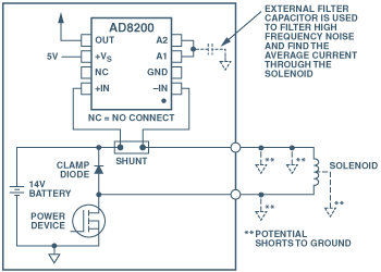
Fortunately, the AD8200 single-supply difference amplifier, with all the desirable properties for this application-complete in a single IC package-is available from Analog Devices. Figure 4 shows an example of the AD8200 applied in an ECU to measure current on the high side in this type of application. Here, the AD8200 is used to amplify and filter the small, differential voltage from the shunt, while rejecting the large common-mode swings mentioned above. The AD8200 can be used in any of the configurations shown earlier.

Figure 4. Electronic control unit, using the AD8200, with low-side solenoid and high-side switching and sensing.
The AD8200 uses a single +5 V supply and has an input common-mode voltage range extending from –2 V to +24 V, with load dump to +44 V. If higher common-mode range is required, use of another member of the AD8200 family is recommended-for example, the AD8205, with a CMV range of –2 V to +65 V and a gain of 50; or the AD8206 with a CMV range of –2 V to +65 V and a gain of 20 (the same gain as the AD8200).
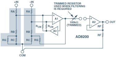
Figure 5. Functional block diagram of the AD8200.
Figure 5 is a functional block diagram of the internal wiring of the AD8200. Before designing a differential amplifier using an inexpensive op-amp and some external resistors, consider that achieving the performance required to measure solenoid current accurately enough for a control application requires a circuit built with resistors that are precisely matched to within 0.01%. The AD8200 has internal laser-trimmed resistors that allow for this level of precise operation when handling both ac and dc voltages. Typical offset- and gain drift in the SOIC package are 6 µV/°C and 10 ppm/°C, respectively. The device also provides a minimum, common-mode rejection of 80 dB from dc to 10 kHz.Besides its availability in the SOIC package, the AD8200 is also available in die form. Both package options are specified over wide temperature ranges, making the AD8200 well suited for use in many automotive and industrial platforms. The SOIC package is specified for –40°C to +125°C and the die is specified from –40°C to +150°C.
The AD8200 also features an externally accessible 100-kΩ resistor at the output of the preamplifier, which can be used with external capacitance for low-pass filter applications, and with external resistors for establishing gains other than the preset gain of 20.
APPENDIX
Mechanical Transmission Control
The older method of controlling transmission shift points involved complex, speed-dependent hydraulic circuits. Shifting was done through the use of changes in hydraulic pressure in a complex valve body. The hydraulic pressure was modulated by a governor attached to the output shaft. Centrifugal force moved the governor, releasing transmission oil and increasing the pressure in the valve body. The method of adapting to changing driving conditions typically consisted of forcing the transmission to downshift under heavy acceleration or loading with mechanical actuators.
When the driver needed more acceleration, the requirement was typically transmitted via a down-shift mechanism, consisting of a rod running from the throttle control in the engine compartment to the side of the transmission. The rod moved a lever, closing off a series of channels in the throttle body. This forced the transmission to downshift under heavy acceleration until, at speed, the governor overrode the down-shift mechanism.
Adapting to changes in load was accomplished using a vacuum modulator. With increasing load on the engine, the vacuum change caused a rod to slide in or out of the valve body, changing the transmission shift point and shift speed. While these methods of controlling shift points and shift smoothness worked, there was little that could be done to adjust these parameters to more variable conditions because of the characteristics of the mechanical system used to control them.
发动机控制 相关文章:
- 用电附件过载引发汽车电源设计新思考(02-23)
- 全方位解析汽车发动机技术(03-03)
- 汽车传感器应用现状及发展趋势全分析(02-11)
