汽车控制系统中螺线管电流的测量
时间:02-21
来源:半导体设计
点击:

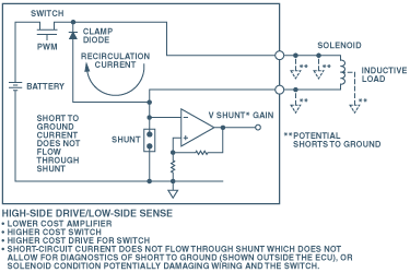
Figure 1. Electronic control unit with high-side switchingand low-side sensing.
When considering this approach, the designer must take into account these disadvantages:The solenoid recirculating current is not included in the measurement, so this circuit provides an inaccurate measure of the average current through the solenoid coil. The solenoid recirculation current can be an aid to detecting solenoid health; if some of the windings have begun to short, the condition can be seen by measuring the passively controlled recirculation current.
Because the switch is on the high side, it is more expensive to buy and to drive. The PWM drive requires careful level translation between the logic output of the microcontroller and the gate.
Additional circuitry is needed to detect shorts to ground because the short-circuit currents do not flow through the shunt. Damage to the wiring and the FET can occur if shorts to ground (Figure 1) are not detected.
The measurement may be unstable because, in practice, ground is not the ideal universal connection, graphically rendered as a little inverted triangle. In the actual application, "ground" may not in fact be ground. Voltage drops caused by currents between the op-amp’s ground and the shunt ground can cause significant errors.
High-Side Current Sensing with a Low-Side Switch
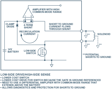
A better method of driving the solenoid is to use a switch that is referenced to ground (Figure 2), allowing the use of a less expensive, low-side switch.
Significantly better diagnostics are possible because the solenoid recirculation current is included in the measurement. In addition, the drive is less expensive, because it is not necessary to perform level translation to the gate.

Figure 2. Electronic control unit with low-side switching and high-side sensing.
However, the amplifier must have high, common-mode rejection, and it must be able to stand off significant common-mode voltage (CMV). The voltage level at the shunt in this example varies from battery voltage to battery-voltage-plus-a-diode-drop. Here’s the explanation: When the switch is closed, the common-mode voltage level at the shunt remains at the low impedance battery voltage. When the switch is opened, the voltage across the solenoid reverses because of the solenoid’s inductance, and causes the common-mode voltage level to include the clamping diode drop-while the transient current flows-before settling to the battery voltage.An important benefit of this drive method is that it allows detection of shorts to ground, because the high-side current flows through the shunt-as seen in Figure 2.
A key concern when using this current sensing method is that the high side of the battery is always connected to the solenoid. This could allow the solenoid to switch unexpectedly if there is an intermittent short to ground. Also, the continuous presence of the voltage at the solenoid could cause excessive corrosion over time.
High-Side Current Sensing with a High-Side Switch
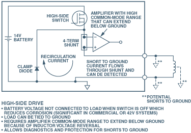
A configuration that minimizes the possibility of unexpected solenoid activation and excessive corrosion is shown in Figure 3, where both the switch and the shunt are connected on the high side. This removes the battery voltage from the solenoid when the switch is off, preventing damage from potential shorts to ground, and allows the recirculating current to be included in the measurement. The battery voltage is removed from the load when the switch is open, so corrosive effects caused by the voltage differential are eliminated.

Figure 3. Electronic control unit with low-side
发动机控制 相关文章:
- 用电附件过载引发汽车电源设计新思考(02-23)
- 全方位解析汽车发动机技术(03-03)
- 汽车传感器应用现状及发展趋势全分析(02-11)
