IP驱动的世界里如何进行电源管理?
今天,一个SOC可以有多个相同的IP,也可以有多个来自不同供应商的不同的IP。每一个IP都可以在一个单独的模式中工作,所以在每一个IP在正式使用的时候都需要专门的电源分配方案。如果电源分配方案确定的太早,将需要根据目标技术重新制定。现在,想象一下你在为来自多个供应商的大量的IP制定实现阶段的电源分配和管理方案;你可能认为它是几乎是不可能的,因为它的验证和调试将会是噩梦般的存在。电源分配和管理需要通过一个自上而下的方式,先完成顶层的抽象设计,再实现底层的各个细节设计。这是今年DVCon上的技术论文,它提供了一个非常有效的用于实现电源管理意图方法。
The successive refinement methodology employs three stages of an IP. The power intent for the IP at each stage is specified in an UPF (Unified Power Format) file at an appropriate level according to a strategy for successive refinement of the power intent.
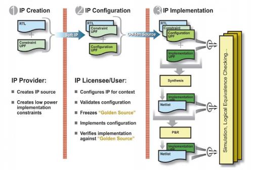
The first stage is the IP Creation Stage when the most abstract view of the power intent is created by the IP provider. This abstract view is represented in a Constraint UPF file that contains the constraints on the power intent of the design (RTL). The power domain is defined at the ‘atomic’ level which cannot be further partitioned by the IP consumer. If the user intends to use retention in her/his power management scheme, then she/he must specify about the ‘retention constraints’ in terms of state elements to be retained.
Similarly, the Constraint UPF file should specify the ‘isolation constraints’ in terms of isolation clamp values that must be used if the user decides to shut down portions of the system as part of the power management scheme. Also fundamental power states of an IP block and its component domains should be defined in a technology-independent manner, i.e. without any reference to voltage levels. The ‘power states’ should be defined without any imposition on the IP consumer about the power management approach to be used. The Constraint UPF file should not be replaced or changed by the IP consumer.
The second stage is the IP Configuration Stage when the IP licensee or end user describes application-specific configuration of the UPF constraints in a Configuration UPF file. The Configuration UPF file contains details of the power management scheme for the system including design ports that a design may use to control power management logic, isolation and retention strategies on power domains along with their control logic, logic expressions on power domain states to reflect control inputs, and so on. The logical control signals may include signals for isolation and retention cells, and signals that will eventually control power switches when they are defined as part of implementation. The Configuration UPF file is required for simulation.
The third stage is the IP Implementation Stage when the end user describes technology-specific implementation of the UPF configuration in an Implementation UPF file. The Implementation UPF file contains details of the implementation such as power switches and voltage rails (i.e. supply network). It defines which supply nets specified by the implementation engineer are connected to the supply sets defined for each power domain. The technology references such as voltage values and cell references are part of Implementation UPF.
This scheme is well structured where power intent defined in constraint and configuration UPF files can be applied to different implementations that differ in technology details. The Configuration UPF loads in the Constraint UPF for each IP so that the tools can check that the constrain
- 调查显示:Fabless IC业者最大IP来源是晶圆代工厂(02-24)
- Gartner称iPad等平板电脑致PC增速放缓(03-07)
- 分析师称平板市场正形成泡沫 不久后将破裂(03-10)
- 消费电子“鸦片”让中国IC很上瘾(03-11)
- Excelitas Technologies宣布SiPM技术取得突破性性成果(03-24)
- 本土芯片商掘金平板市场(05-05)