How to understand this "integrated passive filter"
时间:04-10
整理:3721RD
点击:
The paper, "Design of RF Filters Using Silicon Integrated Passive Components" appeard in "2004 Topical Meeting on Silicon Monolithic Integrated Circuits in RF Systems", shows a design of lumped RF bandpass filter using spiral inductors and mim capacitors.
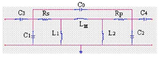
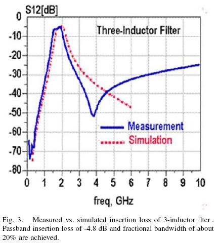
The bottom pic shows the circuit of this BPF together with simulation and test results in this paper.
The authors says L1 and L2 are 2.5nH each and Lm is 10.7nH.
L1C1 and L2C2 determine the location of poles at 1.9Ghz. C3 and C3 are used for matching and also filtering at low frequecies. The bridging capacitor C0 is optional and is used to generate a transmission zero. But values of these three capacitors are not given in this paper.
---But I cannot understand why this circuit topology is used. In standard BPF, e.g. Butterworth or Chebyshev, Lm is usually series connected with a capacitor and their product is fixed by center frequency. I find problems as i can get results
in ADS simulation after several times tuning these capacitors, i only get a very wide band BPF.
Can anyone give me some ideas? Thankyou!
It could be that Lm is a mutal inductance, resulting from the coupling of L1 and L2.
That may be difficult to avoid in an integrated filter, and would preclude the series cap you mention.
this is a crossing-coupling filter.
L1 and L2 are 2.5nH each,
Lm is 10.7nH.
than what's the K between L1 and L2
understand passive filter 相关文章:
- Trying to understand mismatched antenna behaviour above 20GHz without equipment.
- Help in understanding the paper "Understanding Wide-band MOS transistors"
- Understanding of noise figure
- Need help understanding an LNA design method
- Understanding how to translate standards to system requirements
- Is it right to understand the Zopt(optimized noise impedance)of ind degenarated lna