How to reduce the jitter of a pll
i have design a pll using a 9-stage ring oscillator, but the jitter of output signal is large. what are the methods to reduce the jitter in general?
thanks
check the loop filter band width , and see the control voltage of the VCO , is there any rippls on it
and u can an extra RC section , but be aware for the PLL phase margin to insure stability of the PLL
khouly
my pll circuit is below
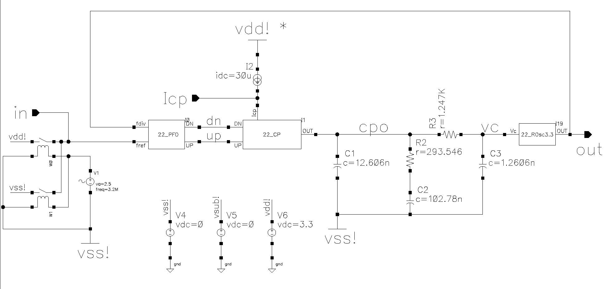
i have design 20khz bandwidth, 45 degree phase margin, but the jitter is about 4 ns peak-to-peak yet. need i reduce the bandwidth further?
i donot know what is the main jetter source , but if it is the VCO , u will need to increase the band width
is there any reference spurs or not
khouly
the reference signal is ideal
because i simulate the it's transient reponse, the vco's nonideal isn't present
i think that the main cause is vco's control voltage it's ripple is large
as below
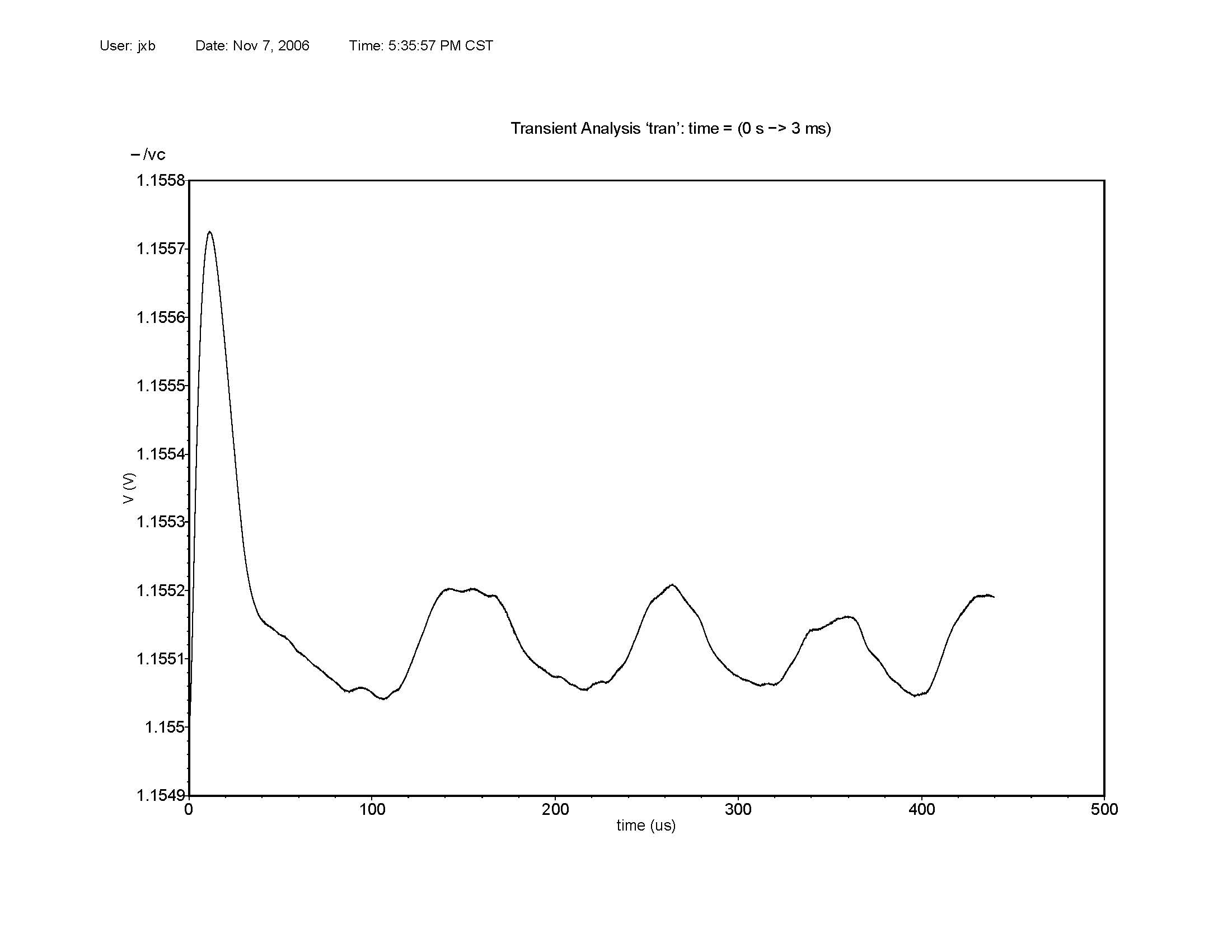
yeah the VCO control voltage has a ripple , so u need to adjust the filter valuse to minimize this effect
khouly
you'r right, i will try it
maybe i can reduce the ripple through decreasing the gain of vco
Am I wrong or the ripple in the control voltage is around 100nV?
Are you sure about this values? What tecnologu are you using?
Bye
it is arroud 100uv , not nv
may be the KVCO is very high so the any ripples on the control voltage will affect the frequency of the VCO
khouly
my kvco is 10.2MHz/V, maybe it's too high
may i using higher order loop filter to reduce the ripple voltage?
it is not so high , but if u can make it less , may b it will help
khouly
i found that when i reduce the gain of vco, the control voltage of vco swing larger
maybe the loop filter need to design carefully
yeah , then adjust the loop filter
try to reduce the BW and see what happen
khouly
hi khouly
i adjust the gain of vco, and change the bandwidth of loop filter
but the ripple of vco's control voltage is present yet
maybe the mismatch of charge pump's source & sink currents results, the spurs?
i will try it
Increase c1 and see what will happen.
hi hackjiang
the cause is the mismatch of charge pump current
increasing c1 will change the system's transfer function
if the source is CP current mismatch , so u need to adjust the source of mismatch , or tey to modify ur CP circuit to get less mismatch
khouly
That does not look like "phase jitter". That looks a lot like your control loop is ringing (and almost completely unstable) at around a 10 KHz open loop bandwidth.
Try changing R2 fro 293 to 2200 ohms and resimulate and let us know if the "jitter" goes away.
With your existing design, you have a control loop zero at 33 KHz, which is not doing anything to help the stability problem down at 10 KHz.