hartley image reject structure
时间:04-10
整理:3721RD
点击:
hey guys below is the block diagram of hartley image reject structure
what i want to know is why is only image signal inverted after the mixer stage..why doesnt wanted signal undergo inversion....please help me out as i cant understand the reason behind this
what i want to know is why is only image signal inverted after the mixer stage..why doesnt wanted signal undergo inversion....please help me out as i cant understand the reason behind this
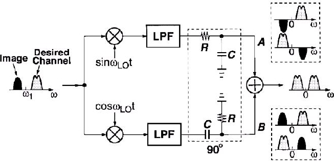
Omega1 is the middle frequency, Image is lower it, and Desired Channel is Higher then Omega1.
Example for lower net on the picture:
For Image:
cos(Omega+Omega1)*t*cos(Omega*t)=0.5*[cos(Omega1*t)+cos(2*Omega*t+Omega1*t)]
here is no change of phase.
For Desired Channel:
cos(Omega-Omega1)*t*cos(Omega*t)=0.5*[cos(Omega1*t)+cos(2*Omega*t+Omega1*t)]
here is an inversion.
still not clear
btw i dont see any difference in equations that you wrote for the image and wanted channel
can anyone help please