Someone recommends me resistors for high frequency uses?
I need resistors working at high frequency(0-7GHz at least). Especially a low parasite capacitance is required, better to be smaller than 50fF. Actually I've found 'partial wraparound thick film chip resistor' from IMS is quite suitable for my case but they ask me to order 100 pieces min for each value and 100 dollars for freight. I just need around 10 PCs for the prototype and that's really over my budget.
So could anyone help me to recommend suitable resistors? Thanks a lot!
Best Regards.
Kevin
when I last modeled standard 0402 and 0603 resistors I thought I was getting values of parallel parasitic capacitance (i.e. across the terminals) of < .05 pF... but my memory may fail me.
have you tried making simplistic models of standard parts and using that in your simulations/design?
Lance
Thanks lance,
yes, I modeled the 350Ohms KOA 0603 RK73B1.Here is the curve:
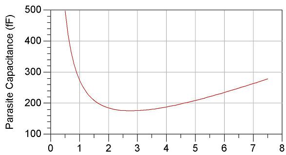
Can you explain why the curve shoots up so dramatically at DC?
is this a shunt circuit?
I've always made this measurement using a series circuit in microstrip, looking at coupling rather than capacitance per se.
Lance
The model I am using to simulate is taken from modelithics select. I also saw the it shows an capacitance that is in parallel with the resistor film from other sources though I am not really understand. I think it should be related to the structure of a TFR resistor or the process.
I guess the question is, what is your test circuit?
do you have the resistor to ground and you're post-processing to get the capacitance across the terminals that way, or is it in a series circuit?
I guess if you're using the modelithics model you can do it without any microstrip... but I'm having a hard time understanding the asymptote at DC if it is not numerical/measurement error.
See what I mean?
Lance
I just connect the resistor with two terms in ADS and sweeped the frequency range to see the variation of paracisite capacitance by calculating from the imaginary part of Zin. Is there something wrong with the circuit?
no, I don't think so.
If you were doing this based on measurement data (correlating to a simulated circuit) or EM simulated stuff, I think you would have to be more careful, but if it is a pure two-terminal model I don't see anything that should go wrong.
what are the parameters of your substrate?
Have you compared the parasitic capacitance of any other models of physically similar parts?
The substrate I am using is RF-60A, which has a charactoristic of εr=6.15, H=1.52, T=0.035mm and tanD=0.0018.
Yes I compared with the model given in ADS (TFR) and they gave more or less the same performance. And I also compared them with the PW-TFR resistor that I mentioned in my question by checking its S2P file. Obviously this one is much better at high frequency.
resistors recommends frequency 相关文章:
- Resistors in N-Way Wilkinson Power Combiner
- What type of resistors, inductors, and capacitors to use for 2 GHz LNA design?
- Thin Film Resistors for Broad band Applications
- Replacing base resistors in RF amplifier
- What is the purpose of three zero-Ohm resistors on the output of 10GHz oscillator?
- Where to get SMD resistors and capacitors? Prototyping/Ads momentum