What is the purpose of three zero-Ohm resistors on the output of 10GHz oscillator?
Here is the image:
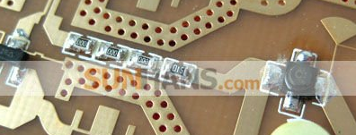
From right to left: "510" "000" "000" "000", there is DRO on the right, and the rest of schematic on the left.
Perhaps in some cases, Power exceeds the resistor spec so sharing could be used with smaller values.
Maybe... But there is NEC transistor with marking "C", that used in some receiving LNA's. I doubt it output can be so high, that it warm up or melt resistor. I think this "C" transistor melt up first if it was able to provide such power :)
SMD resistors has significant parasitics at 10GHz. Three 000 resistor in series can even form a low pass filter.
Here is article describing properties of such resistors at microwave frequencies:
http://www.vishay.com/docs/28871/res...crowaveapp.pdf
I don't agree with the parasitic low pass filter idea. The resistor width is more or less the same as the 50 Ohm line width, so they behave just like a piece of line. I think they are just used as a dummy (placeholder) because the designer wasn't sure what matching elements me might need to add in during the prototypoing phase. And then he discovered the design was fine, and no such extra elements where needed.
At least there are better ways to make a well-defined low pass filter than placing zero-ohm resistors. The resistors are smaller than the basic trace and also add some substrate thickness, so there will be an impedance effect. But I also see it as a variable matching circuit.
For a serious discussion, we would need to analyze the circuit.
They might be placed for some optional purposes..?