srd pulse
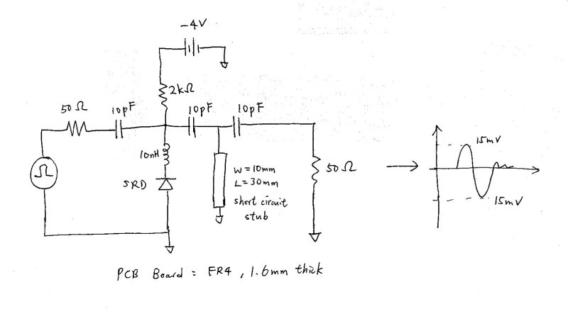
I have been asking for help of pulse generator using Step Recovery Diode(SRD). Recently, I make a circuit but the output amplitude is very small(30mV pk-pk). Which part is wrong? I attach the circuit diagram and the output waveform here. The input signal is 10MHz square wave generated from lab. equipment.
I would move the inductor to where the 10 pF capacitor is.
biff,
I have tried your suggestion but no signal comes out. Is this possible to amplify the small signal?
ttse7
http://uwb.freeservers.com/FIRST/index3.html :D
What is the input frequency? Maybe your inductor value is too big.
Are you driving it with enough power. Probably need > +23 dBm.
-4 volts may be too big. Might need to be smaller, maybe near zero.
The inductor serves 2 purposes. First, it is a simple lowpass filter, so that the higher frequency spike energy goes out the output, and not the input. Secondly, when the srd abruptly shuts off, it is the inductor itself that forms the voltage spike (due to the collapsing magnetic field).
One thing you can do is to remove the transmission line pulse forming network temporarily and work only on the SRD portion of the circuit. When you have a big pulse coming out of the SRD portion, then add back the transmission line circuit to make it narrower.
mirabella2,
The article in the link is russian but the idea is simple.
To Biff4, your idea refreshes my mind and your help is useful.
Best regards,
ttse7
You have received the answer to the question?
To translate you this article?
your input frequency is 10 MHz, 10pf in the input side is small, use a 1nF
The more I think of it, I think it is important that the SRD be driven by a shunt capacitor, and THEN a series inductor, then the SRD. The inductor provides the spike of voltage, and the shunt capacitor provides a broadband ground for the far end of the inductor.
mirabella2,
I think I can get the idea from the article. I have ordered the components. Are you a russian girl?
Added after 4 minutes:
has_ajam,
I have not tried to modify the value of the input cap. to 1nF. Let try next week. I have deleted the short circuit stub and found the shapened output waveform voltage dropped to 0.1V. Remember the 10MHz input square wave amplitude is 5V. Does that mean the current comes from the square wave is not high enough.
You have received the answer to the question?
To translate you this article?