微波EDA网,见证研发工程师的成长!
首页 > 研发问答 > 微波和射频技术 > 天线设计和射频技术 > Balanced Amolifier [hlp]

Balanced Amolifier [hlp]

时间:04-09 整理:3721RD 点击:
Hello Everyone;
Suppose that in the following balanced amplifier, gain of each amplifier is G dB.
Also suppose that 90° Hybrids are ideal. What is the Pout vs Pin? 'Please write your reason.

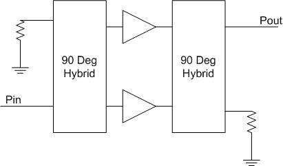
Pout = (Pin-3dB)+G+3dB = Pin+G dBm

where, (Pin-3dB)+G is the output power of one amplifier.

Hi

You will not et more power, because they are in parallel.
Your compression point will be 3-db higher.

Regards

Hello;
hmsheng wrote:
What's about the second hybrid? Do you encounter the 3dB loss by second hybrid?

Hi

The 3-dB is not loss. The first hybrid splits the signal equally (3-dB) and the second combine the two signals. So there is no loss....of course in real life the hybrid have losses about 0.3 dB depending on type.

Regards

What's about the second hybrid? Do you encounter the 3dB loss by second hybrid?

It is given that the hybrid is ideal, so if consider the total power at input and output there is no loss at all!

You do get higher uncompressed output power, 3dB higher. But your gain will be the same as from just the single one.

Your Pout will be: Pout[dBm] = Pin[dBm] + G[dB].

You only gain like before said, higher uncompressed power, but then again you have to feed the input with 3dB higher power to get the full use of the amp. This is done when certain output power is needed. But if you cant change your input level and have to increase your uncompressed output power, you need higher gain in the balanced amp or put a driver amp. before the input stage of the balanced amp.

the power combingin techniques , jsut to do one of 2 , increase the band width l, and increase the output power , but still the gain of the 2 will be the same as 1 , as all said , the output power will be doubled "increase by 3 db"

khouly

Hi,

Besides the compression point issue, the balanced topology has the "golden" property that the match at input and at output of an balanced amplifier is almost perfect regardless the matchings of the original (single) amplifier.

This is often used with LNAs who are heavily optimized for noise, thus input VSWR could be in the range of 5-6. Balanced topology can reduce this to as low as 1.1 (depending of the qualitiy of 90deg hybrid)!

Speaking in dBs, input (output) match of the balanced topology presented on your picture is twice the return loss of a single load plus the isolation between the inputs/outputs.

flyhigh

yeah ur right flyhigh , i have designed LNA for 7 GHz receiver , the LNA matching was for optimum noise the S11 of the lna was about -5 dB , which mea very bad power matching

soon , i will make it balanced in simulation , and i will implemet it

khouly

上一篇:Program Clock Reference- Urgent help needed!!
下一篇:最后一页

Balanced Amolifier hlp 相关文章:

栏目分类
热门文章

Copyright © 2017-2020 微波EDA网 版权所有

网站地图

Top