Which point i should solder in PCB when measure S11 and S22?
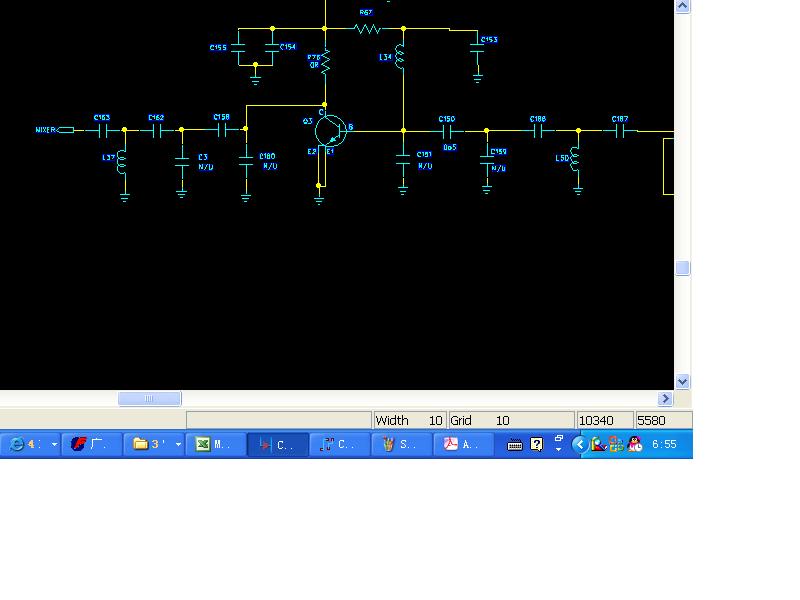
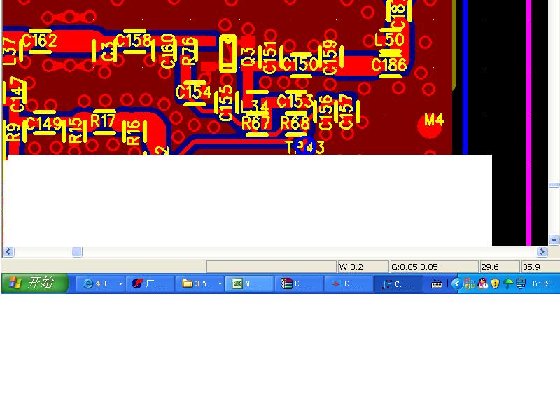
I am a new comer.I want to measure LNA S parameter.But i do not know how to connect my semi-rigid in which point that i can make a correct result,because there are some trace connect between the pads.for example input port C150 and C186 there is a trace,and which point i can solder,is it C150 right pad or C186 left pad?what is the difference?.Anyone can tell me how to do as the attached ?Thanks
anybody help me?
What is your system impedance? 50 Ohm or 75 Ohm?
If you wan to measure the S11 , I suggest that you can solder at the point which connect C187, C186 ,L50.
If you wan to measure the S22 , I suggest that you can solder at the point which connect C162, C163 ,L37.
Thank you for reply.We use the reference resistor:50 Ohm.Can you kindly tell me the reason that you solder in that point.For S11 simulation,we connect the 50 Ohm to C150.but in PCB,we have to add a trace to connect C186.
Of course, the best thing is to use an actual coaxial connector on the board. Do not know what you have for input/output, but sometimes you can sneak in an edge-mount SMA.
But I have had some luck simply using a semi-flex type cable, maybe 6 inches long, with female SMAs on either end. I cut it in half. Then I cut back the outer conductor by around 0.1". I then scape off some solder mask on the ground plane, and solder the outer conductor to the board ground plane. I then solder the center contact of the coax to where I want it to go. In your case, I might stand the C187 or C150 on end, and solder the center contact to the top of the chip standing in air. That way you make an ok contact, and the rest of the circuitry on the board is isolated from the LNA you are trying to measure. It appears that there is some ground plane on the top side of your board, so you are in luck. Find a place near C187 or C150 where there is sure to be a ground via hole, and solder the coax on at that point.
Added after 2 minutes:
http://cgi.ebay.com/2-Semiflex-5-SMA...2em118Q2el1247
Do not move the cable around too much or the cap will be damaged. Try to buy the small diameter semiflex. You can do the same with really small diameter semi-rigid cable.
Thank you for kindness.It is a difficult for me to distinguish the input port or output port between filter and LNA in PCB that is different with schematics for trace.If i can do it,it is easy to compare the test result with simulation.how can i do it?