50MHz LPF?
I have found this http://www.oz1dpr.com/html/website/low%20p.jpg and schematic here http://www.oz1dpr.com/html/website/filter.html
I was wondering if you have anything better to propose and also if air wound coils are better than SMD or commercial "resistor like shape" coils. I think air wound should have greater Q so they may be better but I am not sure.
If you worry about inductor Q, you can go for wirewound "air coil" SMD chips, they have tight tolerances of 5 % or less and achieve Q values of 25 to 50 in the respective inductance and frequency range. This should be sufficient unless you want to design very steep filters. The other aspect of low Q inductances are slight additional passband losses. If your receiver operates noise limited, this can be a reason to use a higher quality filter.
Regarding filter design, I guess you don't need the 1.5 kW power rating of the linked filter?:D So it's basically a standard 5th order low-pass. But you should specify the intended filter properties, to decide which filter type and order is appropriate.
Yes of course there is no need for the door knob capacitors for receiving, I will use standard SM types. I would say the most important issue is the easiness of construction, as the whole receiver is built from scratch with commonly available parts, in order for the amateurs to re-build the whole thing.
Another issue may be the noise, as the preamplifier that I am using has less than 1dB NF. It is 10KHz-220MHz broadband amplifier, so all I need is to attenuate the >50MHz signals in order not to pass through the amplifier, but leaving as much as possible signal of <50MHz to pass through.
1. So based on the requirements and your estimation could you say that the filter I presented you is good enough for such a system?
2. Also, looking at the photo, do I need to put the coils too far appart? To save space, could I put them closer (smaller leads)?
3. Finally, is it better to place the filter on ANTENNA-FILTER-PREAMPLIFIER or on the ANTENNA-PREAMPLIFIER-FILTER place?
Thanks a lot for your help
According to the capacitor values, the filter seems to be equivalent to a 2-3 dB passband ripple Chebyshev filter. The inductance adjustment is rather critical because the highest pole Q is around 7-8.
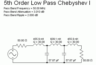
Here"s a circuit of a 1 dB ripple (lower Q) filter with component values rounded to E12.
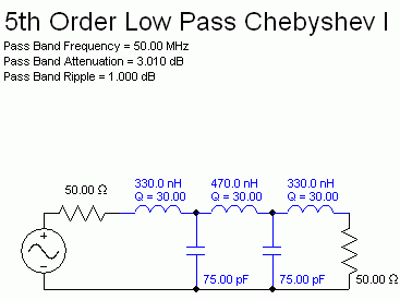
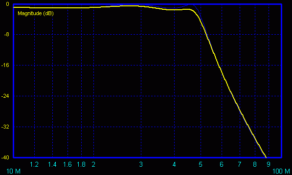
You can see, that the new frequency response (yellow) is slightly degraded due to the modified component values.
To keep higher frequency interferences, e.g. FM radio, out of the amplifier, you should place the filter before the amplifier.
Air coils are better than chip inductors, the best Q is obtained by using toroid.
I know about air coils but I thought that cores generally degrade the Q, that is why in crystal radios they try to use air core coils..
At frequency of below 50 MHz, the core will give you considerably higher Q than air coil. For example, you may use mix-17 material you can obtain Q as high as 200. If using air coil, you would be lucky if you get Q of 100, plus air coil become very big at this frequency. You may also experience a better performance with core for spurious operation as the filed is constrained within the core and much less cross talk between inductors.