750 MHz Band Attenuation Filter
Lumped Components serve well here..No need Microstrip structures..
The Simplest Form is a Parallel LC in series or a Series LC in Parallel or combination of those.But better solution is to use N-stage LC filter approximations ( Butterworth or Chebychev etc. ) then apply Bandstop Transformation.The best method is to use a Filter Design Program..
You need the complete pass- and stop band specification to determine the filter effort, e.g. minimal order.
Lumped Components is a good method. No need Microstrip structures.
Any lumped component Band Pass Filter with central frequency greater than about 500MHz would be very sensitive to component tolerances, to PCB layout, and especially to temperature variations.
May need more space for a 750 MHz microstrip filter, but for sure you will have much less headache designing and manufacturing it.
Actually, I like to combine both discrete and line elements at these frequencies. But as FvM mentioned, without full specs it's not possible to estimate anything.
Series LC usually has some amount of neighboring resistance also in series. It reduces Q.
LC tank has maximum Q due to slight R. It's easier to achieve narrow bandwidth.
Bandwidth is affected by the L:C ratio. These 3 layouts are identical except for having different LC ratios.
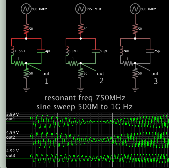
To choose a value, 50 ohms is assumed for input and output resistance.
Your inductors have different Q factor.
MHz Filter Attenuation 相关文章: