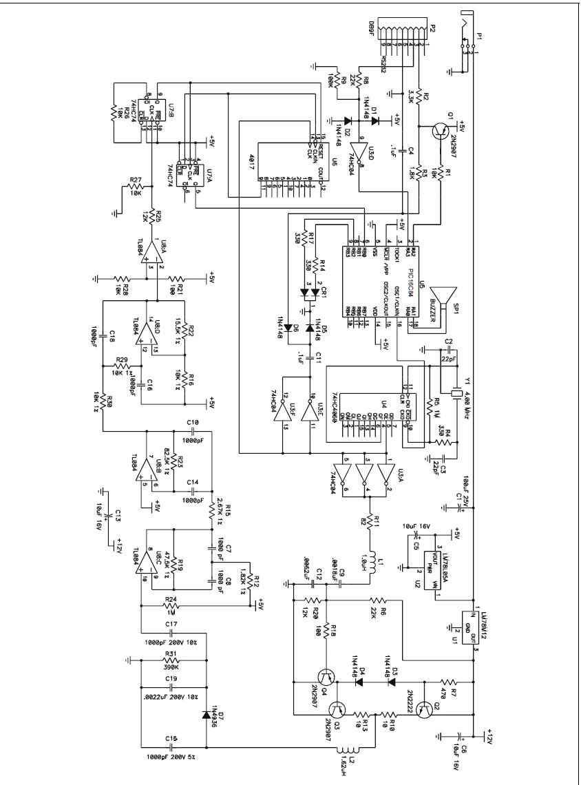
can someone help me check this circuit..
can the 7812 voltage regulator really produce a 12v output?
i hope anybody can help me find a solutionfor this circuit.. thanx!
What makes you thinking there are errors in this circuit?
If you feed ≥15Vdc to P1, the LM78M12 will produce +12V output ..
Rgds,
IanP
sorry..i didn't mention that i intended to supply 9v at p1..
if i use 15v will the 7805 also produce 5v at the same time as 7812 produce 12v?
Yes. And the 7812 can only reduce the voltage so you need around 15V as already mentioned.
Keith
By all means ..
However, because of the voltage difference and current consumption this little gismo can become quite hot and eventually go into thermal shutdown, so it may be safer to use LM7805, not the "L" version ..
Rgds,
IanP
Hi,
It looks like there is a mistake in the inductance of the reader coil L2 (1.62 uH). The push-pull amplifier is being driven with a 125 kHz signal, but the resonance of L2 and C15 is about 4 MHz. The inductance should really be 1.62 mH.
Regards,
Chris
thanx a lot..
i have a few more question
1)can i replace the pic16c84 with pic16f88?i heard that pic16c84 is rarely in stock in my place..can the pic be easily replace in this circuit?
2) can somebody help me explain the circuit after tl084(u8:B)?
hi,
tl084(u8:B) functions as filter for the demodulated signal, & (u8:A) is practically a comparator...
K..
sorry but what i meant was the circuit after tl084(u8:B)...
i.e tl084(u8:D), tl084(u8:A), u7:A, u7;B and 4017